.png.5a0f08430bae173944a56977dd41765f.png)

Muhammed Sarikaya
-
Posts
211 -
Joined
-
Last visited
Everything posted by Muhammed Sarikaya
-
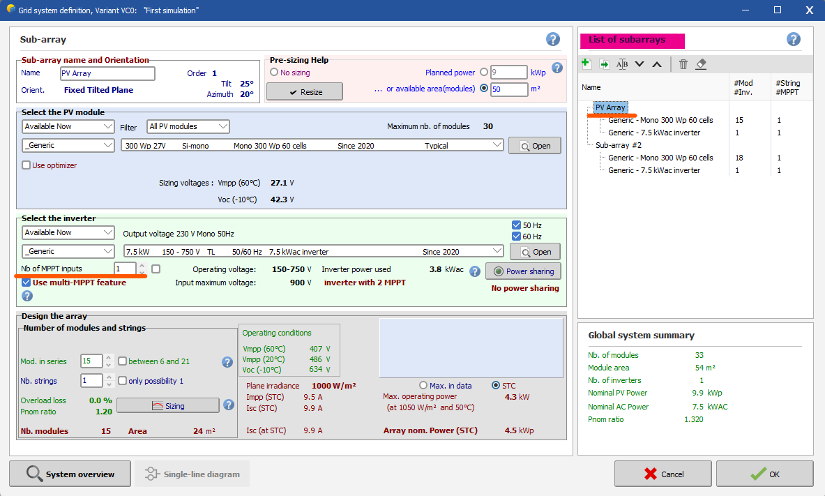
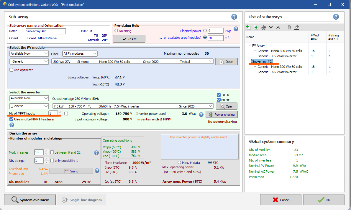
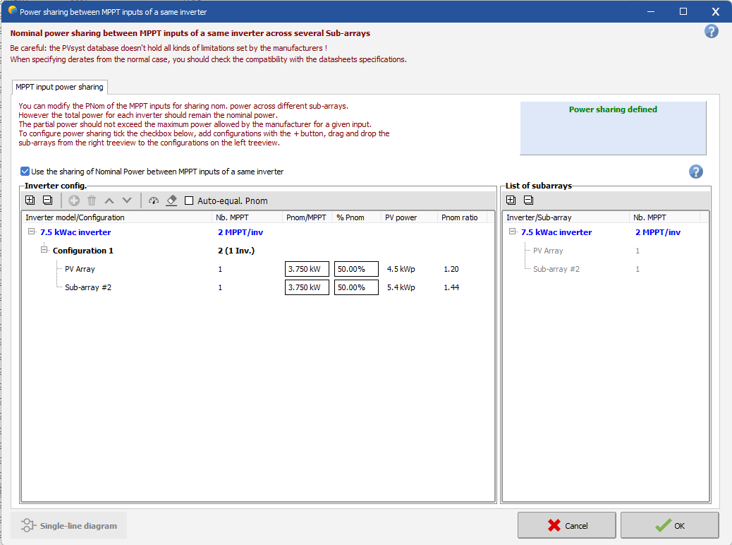
Hi John, I will show you a simple example of how to use the multiple MPPT feature. Let's say you have an inverter with 2 MPPT entries and you want to define each of them. First, you need to create two sub-arrays as below. When you select the first subarray, all the parameters you define are independent of the second subarray. This means that you have to select the second inverter to set all the parameters independently. To begin, the first subarray defines one MPPT entry of your inverter. Be careful, the box labeled "Nb of MPPT inputs" should be set to 1, meaning you are configuring only one MPPT entry of the inverter. You decide to configure 15 modules in series and 1 string. See below: Then, you select the second sub-array and you have to enter "1" in the box "Nb of MPPT inputs" to define only one MPPT entry of the inverter. Also, because its entry is different from the first subarray, we decided to define 18 modules in series and 1 string. See below: Next, you need to set up "Power Sharing." Click on the "Power Sharing" button. Follow these steps to set it up, see below: You have to move the sub-array from the right to the left under the inverter. I hope this helps you understand how to use the multi-MPPT feature and power sharing. Regards, Muhammed Sarikaya

-
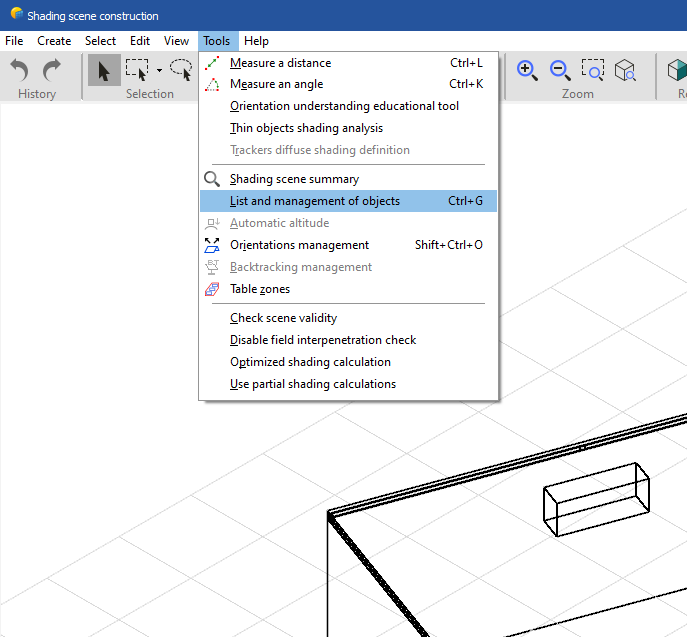
Dear Swonno, I believe you are referring to the tool 'List and Management of Objects,' which is available only in the 3D scene. You can also access it through 'Tools > List and Management of Objects.' See below: Regards, Muhammed Sarikaya
-
Dear Shiwankar, It's not possible to import from Helioscope to PVsyst, and we are not planning to do so. Regards,
-
Dear Swonno, Unfortunately, this is the weakness of the table zone. It's an iterative process; you need to come back and check the number of PV modules and delete them to reach the desired number. Regards, Muhammed Sarikaya
-
Dear Meurville, It's not possible to avoid. Near shading will be calculated for the entire year. Regards,
-

Different number of Panels per string in 1 inverter
Muhammed Sarikaya replied to RCA's topic in How-to
Dear RCA, You can use the multi-MPPT feature and sub-array to configure your project. I invite you to read this help page: https://www.pvsyst.com/help/multi-mppt_more-examples.htm Regards, -
Dear Polasek, I can't say anything at the moment. Could you please send us the project at support@pvsyst.com? I need to investigate and understand why you are experiencing these issues. Regards, Muhammed Sarikaya
-
Dear Dane Archer, In PVsyst, we provide a tool for calculating wiring resistance to estimate approximate ohmic losses. However, there is another way to calculate the total resistivity of your wire on your own. Then, you can enter this result in the following field: Regards, Muhammed Sarikaya
-
Dear Nayah, It's impossible for me to judge and determine why you have this difference. Can you please share your project with us at support@pvsyst.com, mentioning the issue you encountered? Regards, Muhammed Sarikaya
-
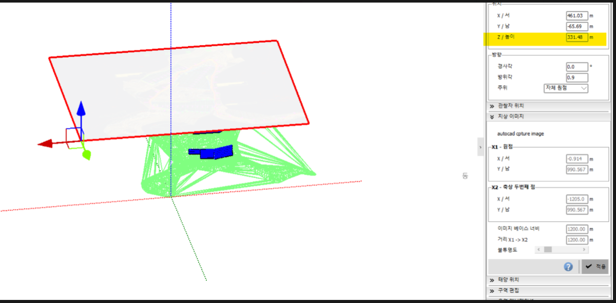
Dear Swonno, Look at this picture and set the highlighted Z value to 0. Regards, Muhammed Sarikaya
-
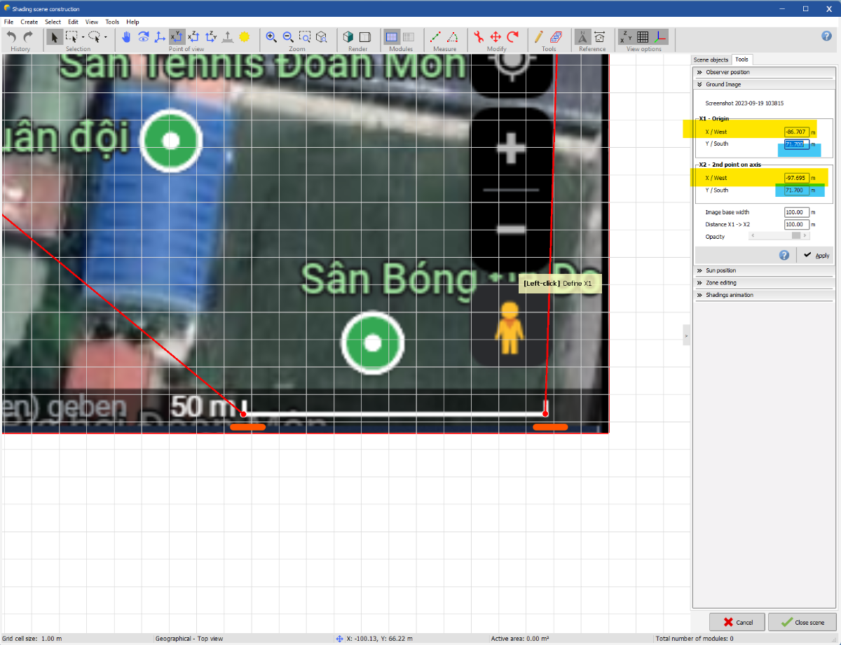
Dear Swonno, I already shared an example. It's important to select X1 and X2 on the scale. Regards, Muhammed Sarikaya
-
Dear Swonno, You missed selecting X1 and X2, which is why you are having trouble adjusting your image. When you import a ground image, it must include the scale. See my example: Be sure to have the same value for Y1 and Y2. Also, don't forget to set the distance between X1 and X2 to match the screenshot of your Google Maps. When you click, the size of your image will be adjusted. Additionally, you can modify the opacity, but don't click on apply. You must add a 2D image in PVsyst. Regards, Muhammed Sarikaya
-
Different azimuth in Near Shadings and Orientation tabs
Muhammed Sarikaya replied to brunok's topic in How-to
Dear Zainol, You can modify the baseline slope. In the near shading window, click on 'Tools' and then on 'List and Management of Objects.' A new window will appear. In the 'Baseline Slope' column, set everything to 0. This way, you will have the same nominal azimuth and tilt that you defined initially. Regards, -
Dear Swonno, Your first question is not clear. Can you explain what you are trying to do? Regarding your second question, by default, the ground object doesn't cause shading, but it is possible to activate it. You need to double-click on your terrain in the right panel and then check the "Enable shadow casting" box, as shown in the example below. Regards, Muhammed Sarikaya
-
Dear Vera, This information is a leftover from the first version of PVsyst. You won't find it in the technical datasheet. Please ignore it. Regards, Muhammed Sarikaya
-
Shading factor table the Blue font display error
Muhammed Sarikaya replied to zhoudaweiman's topic in Shadings and tracking
Dear, I invite you to consulte this help page of PVsyst: https://www.pvsyst.com/help/shadings_factor_table.htm During the elaboration of the shading table, the points (sun positions) located behind the plane of the PV field appear in blue. The highest entry among the blue ones is extrapolated from the above entries. This is to avoid artifacts in the interpolation of the shading factors. Other entries for which the sun arrives behind the plane are marked as "Behind". Regards, Muhammed Sarikaya -
Numbers of Modules in ZOne
Muhammed Sarikaya replied to Muhammad Abbasi's topic in Shadings and tracking
Dear Muhammad, Can you give us an example and explain in detail what you want? Regads, Muhammed Sarikaya -
Dear James, Polygonal tables are not suitable for bifacial systems. I suggest using a full table, but be aware that your shading calculation might be slightly higher than the actual value. Regards,
-
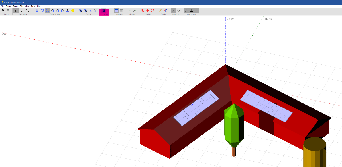
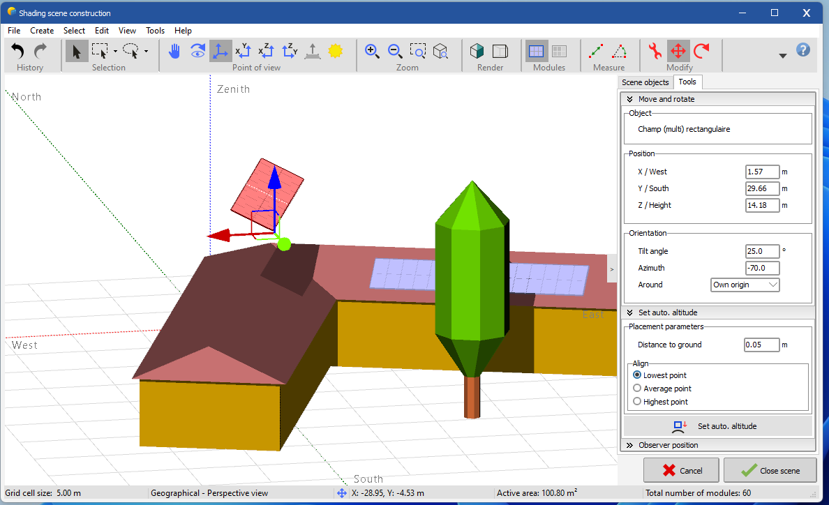
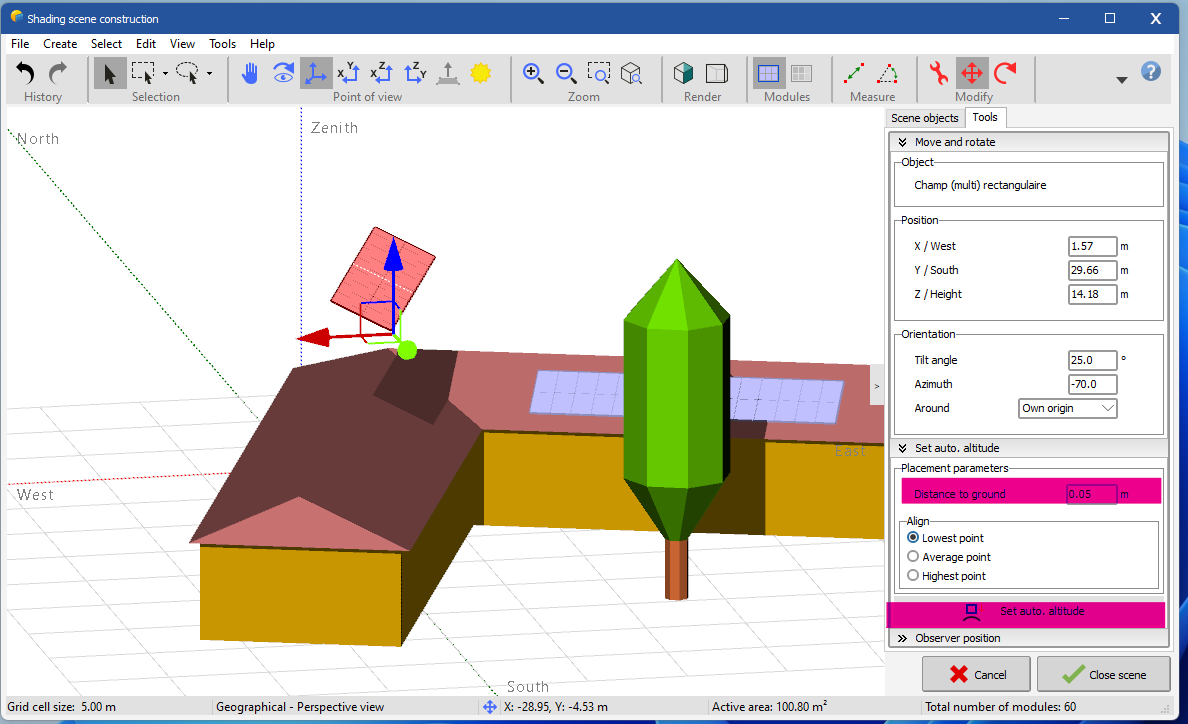
Dear Swonno, There is a technic to work with rooftop. First, activate the button "normal to face" With your mouse, position on the menu point of view and click righ, you will see that you can add the button "normal to face", see my screen shot: It helps you to position normal to the selected face. Very important to know, you have to activate the render "realistics" to acced to this button: Then, click on any surface you want and you noticed that when it selected the color is slightly different. I hope this trick will help you. Also, there is an other tools very helpful, it's "automatic altitude" You can select the PV panel and then select "automatic altitude" A new windows appear at the right in the "tools" panel and you can define the distance from the ground and then, you have to click on the button "Set auto. altitude" Regards, Muhammed Sarikaya
-
Dear James, I understand what you want to do. You need to create a polygonal PV plane. Then, right-click to delete one or more modules when you position the mouse over a PV module. Regards, Muhammed Sarikaya
-
Dear James, Can you explain your procedure for creating this table so I can understand what went wrong? Regards, Muhammed Sarikaya
-
Dear James, Could you please share a screenshot of your system? It's unclear why some modules are missing. Regards, Muhammed Sarikaya
-
Inverter maximum input voltage mismatch with array Voc
Muhammed Sarikaya replied to Irakli Bezhuashvili's topic in How-to
Dear Irakli, First of all, don't modify OND file and PAN file. Your problem is divided in two categories: 1. How to size a PV system with MPPT definition 2. Limits and conditions for sizing a PV system When defining your project, be careful to deactivate the 'MPPT feature' checkbox if you don't plan to configure it. This doesn't mean the software won't calculate based on the maximum power of the PV array. The message 'The array Voc at -10°C is greater than the inverter's absolute maximum input voltage' indicates a major condition that must be respected when defining the PV system. You need to know that the PV array voltage changes with temperature, and if the voltage exceeds the inverter's maximum input voltage on a cold day, it could damage the inverters. You can read more on this help page: https://www.pvsyst.com/help/systemgrid_vocond.htm Regards,
-
Dear Swonno, You can click on these three buttons "X-Y" or "X-Z" or "Z-Y" to displayone side. As a reminder, near shading it not intended for complex drawings. Try to keep it simple, as the purpose is to simulate the shading of objects on your PV plant. Regards, Muhammed Sarikaya
-
Different azimuth in Near Shadings and Orientation tabs
Muhammed Sarikaya replied to brunok's topic in How-to
Dear Irakli, In this case, don't use the topography in PVsyst if you plan to adjust all the supports to have the exact same tilt and azimuth. Regards, Muhammed Sarikaya