.png.5a0f08430bae173944a56977dd41765f.png)

Muhammed Sarikaya
-
Posts
211 -
Joined
-
Last visited
Everything posted by Muhammed Sarikaya
-
Dear Abeer, I imagine you set the orientation angle at 25 degrees, which will remain the same. Then, in the 3D scene, you can add the slope, and for the simulation, the final orientation with the slope added will be used. Could you provide more details about your question? A screenshot would also help me answer you more precisely. Regards, Muhammed Sarikaya
-
 Dear Carlos, I can't see the step where you define the power sharing, so I assume that you have mastered the subject. I can suggest the following steps for the 40 kW inverter with 4 MPPTs: First inverter input: connect 2 strings Second inverter input: connect 1 string Third inverter input: connect 1 string Fourth inverter input: connect 1 string This requires you to create 4 sub-arrays where you define the previous inputs. That means you will have: Sub-array 1: 2 strings Sub-array 2: 1 string Sub-array 3: 1 string Sub-array 4: 1 string This method will allow you to create and use power sharing effectively. If you need more help, don't hesitate to reach out to us. Regards, Muhammed Sarikaya
 -
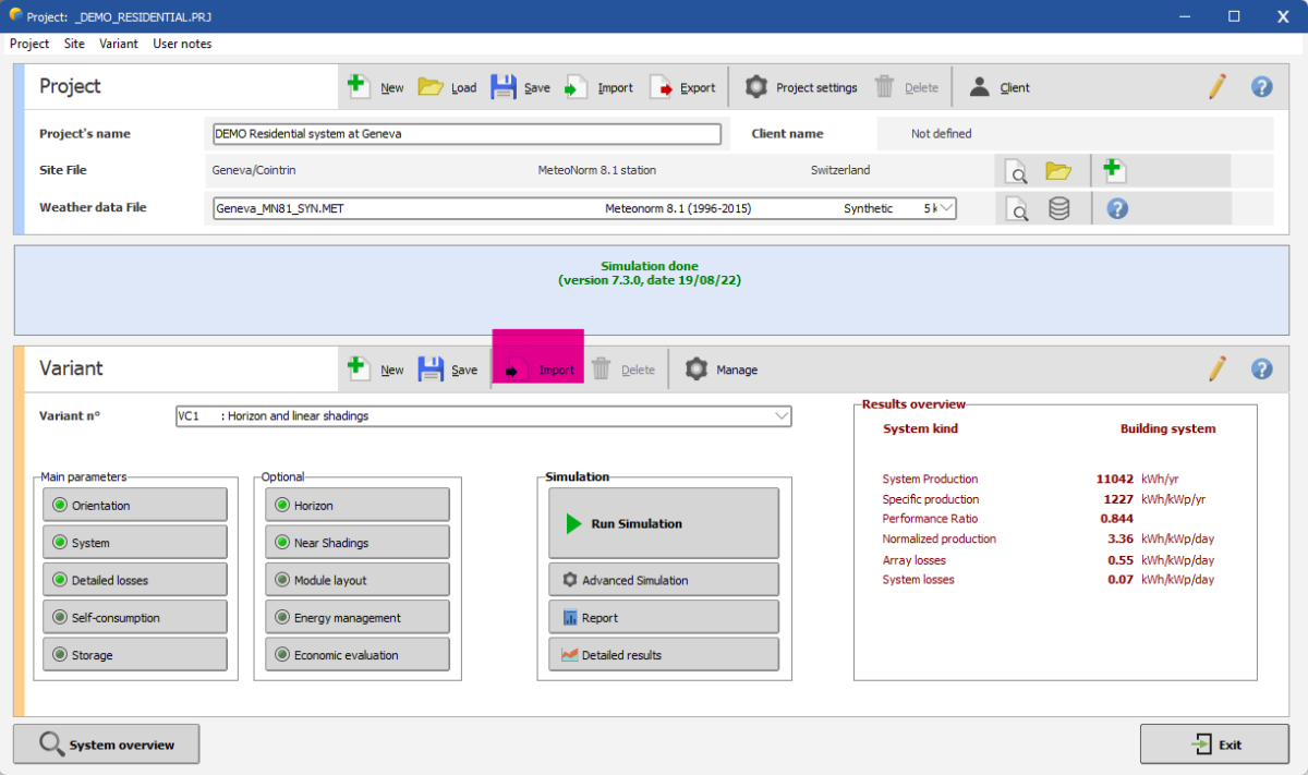
Dear Hampus, You can create a basic variant, and then for each new project, you can import this variant by clicking on 'Import,' as shown below: Regards,

-
Dear Hampus, Unfortunately, we can't set default values for detailed losses and project settings. Regards,
-
Dear Pranav, I don’t understand your project. Could you provide more details about what you intend to do? What is the purpose of having a battery if you don’t use the energy yourself? Does your system inject energy into the grid? If that is the case, why do you need batteries if you can inject all the produced energy directly into the grid? Regards,
-
large-scale project on a curved ground?
Muhammed Sarikaya replied to Abeer's topic in Shadings and tracking
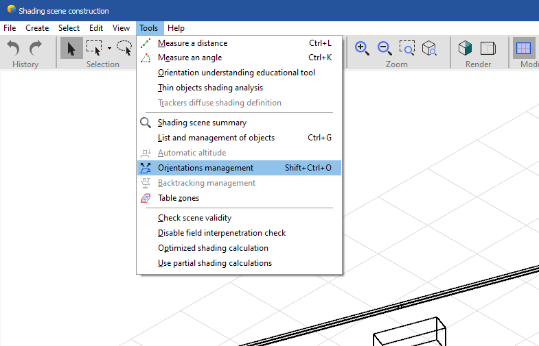
Dear Abeer, In the near shading feature, you can define the topography which has a slope, and then use the 'zone tool' feature to define the position of the PV modules on your terrain. Be careful, as a 4 MW project will require significant computational power and can take a long time to simulate. If you need more precision, don't hesitate to post your question here. Regards, Muhammed Sarikaya -
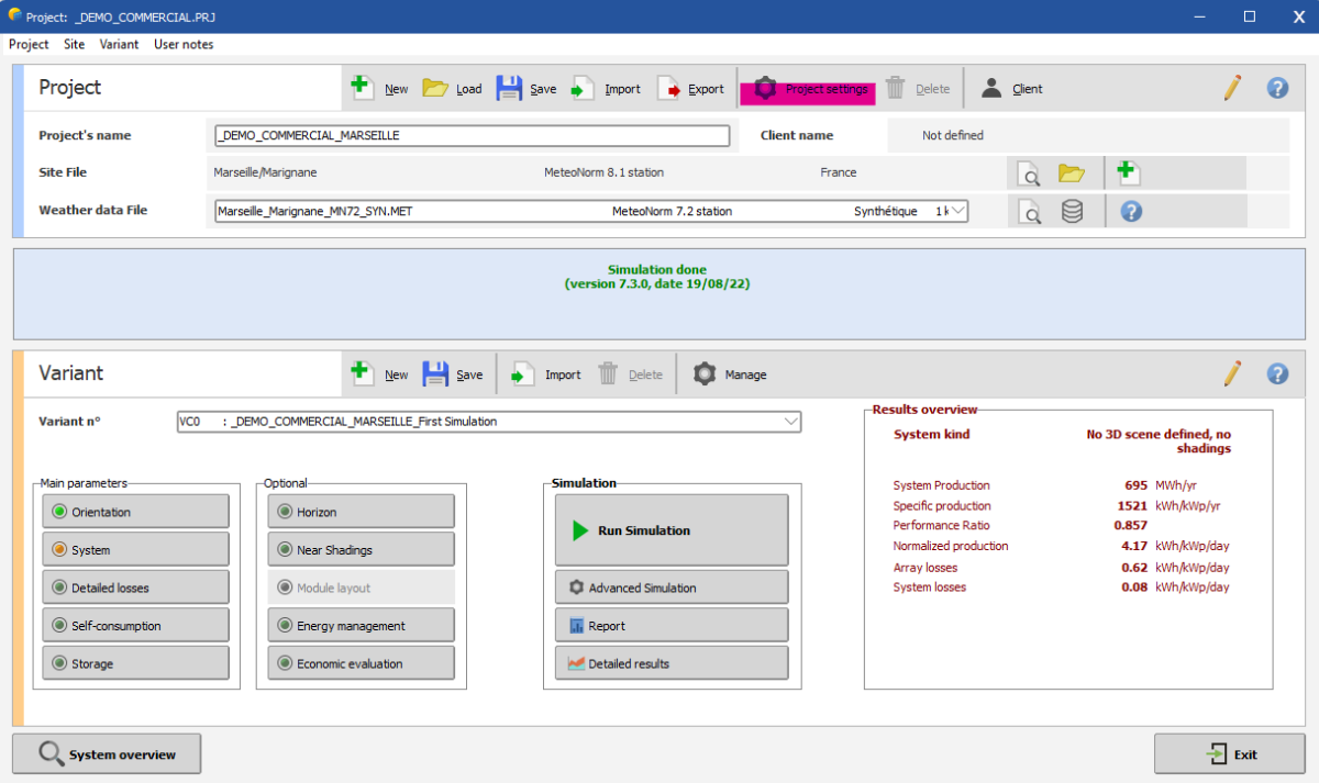
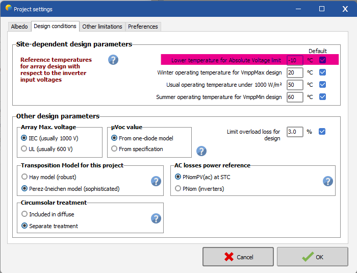
Dear Vasyl, You can adjust this parameter to ensure a lower temperature. Click in "Project settings" Then modify this value: Please don't hesitate to reach out if you need further assistance. Regards, Muhammed Sarikaya
-
Dear Zwonno, I invite you to check out our tutorial on orientation management and base slope: You need to match the PV array with the orientation of the nearby shading scene in the system. Regards, Muhammed Sarikaya
-
BIAFACIAL LOSS INDICATION IN NOT VISIBLE IN LOSS DIAGRAM
Muhammed Sarikaya replied to Ranjit's topic in PV Components
Dear Ranjit, It's possible that you didn't activate the bifacial module. Please follow this tutorial to learn how to use a bifacial PV module: Regards, Muhammed Sarikaya -
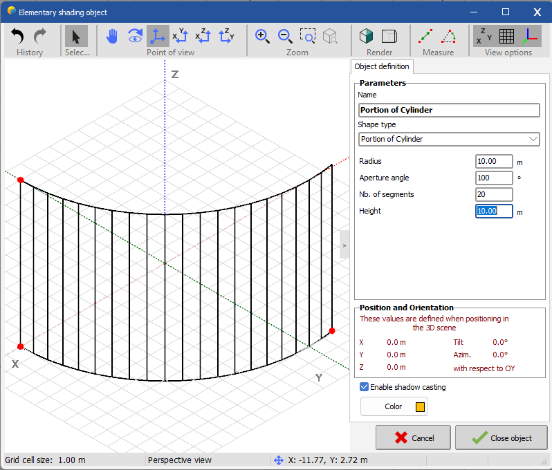
Dear Swonno, Even if it's an ellipse, you can reduce the 'aperture angle,' which will allow you to draw something close to an ellipse. Remember, it's not necessary to create a perfect 3D scene. You are trying to understand the shading effect on your PV array, and a perfect and precise rooftop definition will probably not make a big difference compared to an approximate rooftop definition. Regards, Muhammed Sarikaya
-
Dear Swonno, I suggest using the "near shading" feature with the elementary object "portion of cylinder." Here's an example: You should adjust the "aperture angle" to match your project's requirements. Regards, Muhammed Sarikaya
-
Dear Ben, First of all, in defining the water needs, you specified a maximum flow rate of 8 m³/h. However, the selected pump operates between 40 m³/h and 200 m³/h. Don't you think the pump is oversized for the well? Even if you install the pump at depth, the water availability won't change; the well's resources only allow for a flow rate of 8 m³/h maximum. In real operation, the pump will frequently start and stop because the water level will drop to the level of the pump, and a pump should never operate without water. I suggest you consider replacing this pump with one that has a lower flow rate, more suitable for the well's capacity. Regards, Muhammed Sarikaya
-
Dear Swonno, Unfortunately, it's an iterative process. You have to set it up independently, and there is no way to copy and simplify these things. Regards, Muhammed Sarikaya
-
Dear Swonnon, I don't understand exactly what you want to do. Can you provide more details? Regards, Muhammed Sarikaya
-
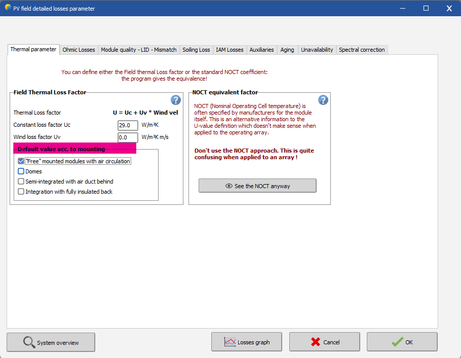
Dear Marc, The racking is not considered in the simulation calculations. Perhaps you are referring to changes in temperature depending on how it is mounted in your project. If this is the case, in the "Detailed Losses" window and under the "Thermal Parameters" tab, there are options for how your system is mounted. Please see the screenshot below: For more help on this topic, you can visit: https://www.pvsyst.com/help/thermal_loss.htm Regards, Muhammed Sarikaya
-
Different number of PV modules/string in the same subfield
Muhammed Sarikaya replied to pontesimo's topic in PV Components
Dear Pontesimo, I invite you to watch our tutorial on how to create different sub-arrays and configure MPPT and power sharing. Regards, Muhammed Sarikaya -
Dear Swonno, First and foremost, you must ensure that the surface area matches between the system definition and the 3D scene. What is your objective? Is the PV area defined in the system the actual PV area, or is it the one you defined in the 3D scene? You must adjust one of them to ensure they match. You can also use the 'Orientation Management' tool in the 3D scene. This tool helps you understand the extent and direction of the orientation. Regards, Muhammed Sarikaya
-
How do I get the inputted albedo to reflect in the report?
Muhammed Sarikaya replied to Vera's topic in How-to
Dear Vera, The albedo you have modified surrounds the entire PV plant. For a bifacial system, you have the option to define the ground albedo beneath the PV modules. I invite you to watch our tutorial on bifacial modules on YouTube, where you will find how to set this ground albedo factor. Here the link: Regards, Muhammed Sarikaya -
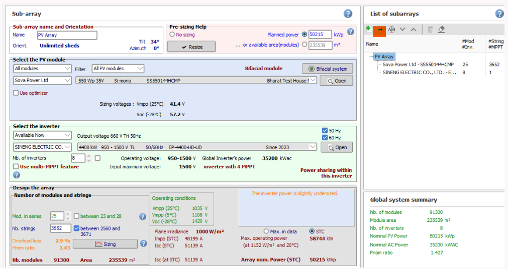
Dear Ranjit, First, click here in the higlighted in orange: Then you will have 2 subarrays. In the first subarray, enter "Nb. of inverters": 6, then in "Mod. in series" enter: 22, and in "Nb. strings" calculate: 6 (inverters) * 21 (strings) * 25 (SCB) = 3150. After that, in the second subarray, enter "Nb. of inverters": 2, then in "Mod. in series" enter: 22, and in "Nb. strings" calculate: 6 (inverters) * 20 (strings) * 25 (SCB) = 3000. We don't define the SCB in PVsyst. If you follow these steps, you will be able to simulate your project. Regards, Muhammed Sarikaya
-
Dear Ranjit, If your connection is consistent between each string, there's no need to mention the SCB. However, if there are differences between strings, you should specify this using sub-array and MPPT features. Can you tell me what your string configuration is? Regards, Muhammed Sarikaya
-
Dear Ranjit, Can you tell me where in PVsyst you are blocked so I can help you? Otherwise, I invite you to watch our tutorial to understand how to create a project in PVsyst. You didn't mention the inverter brand or the PV module brand you want to use. Regards, Muhammed Sarikaya
-
Dear Swonno, "If you have already entered a value in the 'Distance X1->X2' box, do not enter a value in the 'Image base width' box; you should define one or the other, not both. After you have chosen X1 and X2, you can notice the values defined for Y1 and Y2. Simply copy the value from Y1 to Y2. Regards, Muhammed Sarikaya
-
Dear Qasem, I invite you to read our help page about the Pnom ratio: https://www.pvsyst.com/help/index.html?pnomratio.htm Regards, Muhammed Sarikaya
-
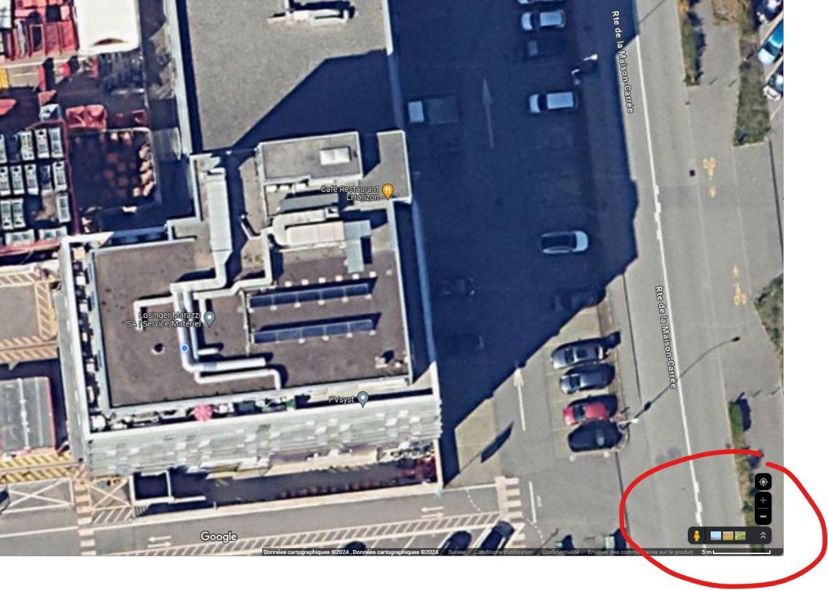
Dear Swonno, When you take a screenshot of a Google satellite image, you must include the scale, which is in the right corner. You can read the distance on this scale, as shown in my example below: You can see that my scale is 5 meters. This is how you determine the distance between x1 and x2. Regards, Muhammed Sarikaya
-
orientation Pamareters
Muhammed Sarikaya replied to mohamed abdelkader's topic in Shadings and tracking
Dear Mohamed, I invite you to watch this tutorial to solve your issues. Please let me know if you succeed. Regards, Muhammed Sarikaya