.png.5a0f08430bae173944a56977dd41765f.png)

Muhammed Sarikaya
-
Posts
211 -
Joined
-
Last visited
Everything posted by Muhammed Sarikaya
-
Dear Irakli, I don't quite understand your question. Could you be more specific about what exactly you want to do? Regards, Muhammed Sarikaya
-
Dear Gordonbrazell, Could you please share the 3D file with us at support@pvsyst.com so that we can investigate and understand what happens when it's imported into PVsyst? Could you also mention in the email the initial orientation you intended? Regards, Muhammed Sarikaya
-
Dear Obulshteyn, Maybe you can send a screenshot of the scene in Lumion. However, I suspect that your scene contains multiple objects, which PVsyst has difficulty opening. The purpose of the 3D scene in PVsyst is to calculate shading on the PV surface. If your Lumion project includes elements that don't impact the PV surface, I suggest removing them. You need to simplify the drawing as much as possible, as excessive details add complexity and could be one of the reasons it fails to open in PVsyst. Regards, Muhammed Sarikaya
-
 Dear Matheus, Only CSV files for topography are accepted in PVsyst. I suggest you find a way to convert your TIFF file into a CSV file with only three columns: X, Y, and Z coordinates. Regards, Muhammed Sarikaya
 -
Dear Obulshteyn, There is no maximum size limitation for importing a DAE file or other files. The ability of your computer to open the 3D scene depends on its configuration (whether it is powerful or not) and the complexity of your drawing—does it have a lot of faces or objects? This could be a limiting factor. To clarify, could you please send us your DAE file at support@pvsyst.com? This will help us identify why you're having issues importing and reading it. Also, I’m not familiar with Lumion; could you explain what it is? Regards, Muhammed Sarikaya
-
Dear Obulshteyn, I suggest designing your PV panel in PVsyst. After that, you can press "Ctrl+G" to view the position of all your PV tables. Once you find the right position, you can extract this data and redraw it in the software of your choice. Regards,
-
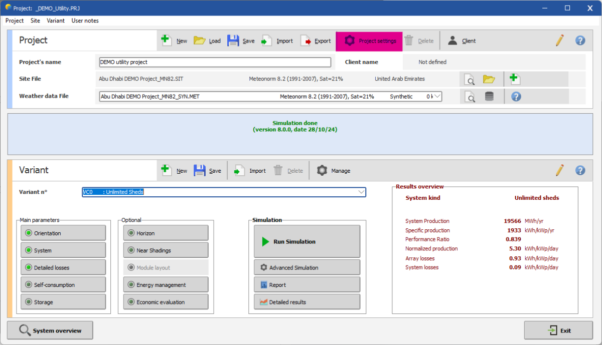
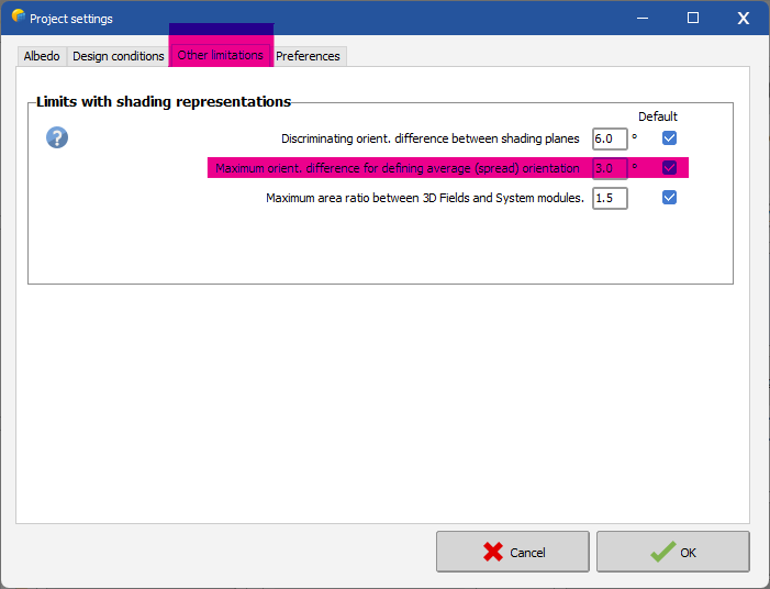
Dear, Please click on "Project Settings." Then click on "Other Limitations." After that, you can adjust this limit to avoid the issue. Regards,

-
Dear Jackson White, Could you please send your project to support@pvsyst.com? We can investigate to better understand your issue. Regards,
-
Dear Tanat, You can read this forum link on the topic: Regards, Muhammed Sarikaya
-
8.0 Version can't run from the first loading page.
Muhammed Sarikaya replied to Swonno's topic in How-to
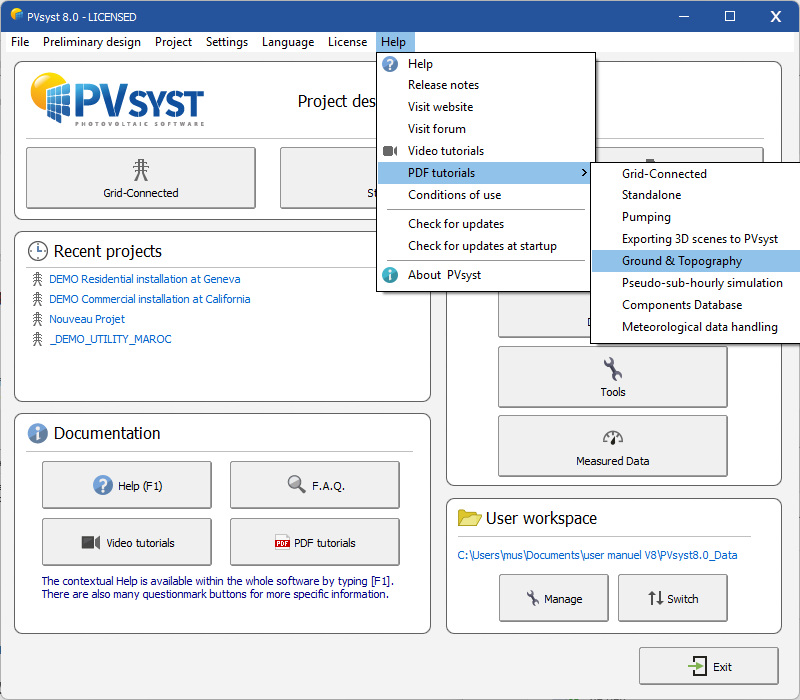
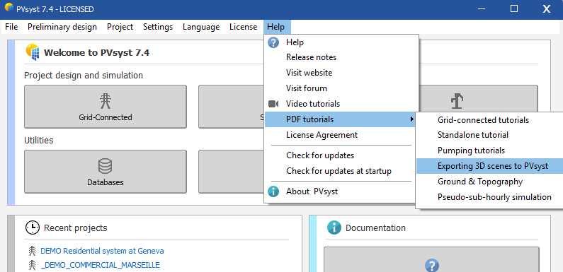
Dear Swonno, Here is a tutorial you can follow: Regards, Muhammed Sarikaya
-
Dear Eric, I encourage you to read this forum to resolve your issue: Regards, Muhammed Sarikaya
-
Dear Stephen, Yes, it's possible to use both versions on the same computer. Regards, Muhammed Sarikaya
-
Dear Dany, In stand-alone design, it is not possible to remove the batteries. Regards,
-
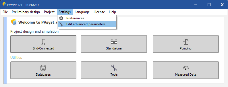
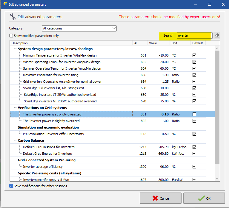
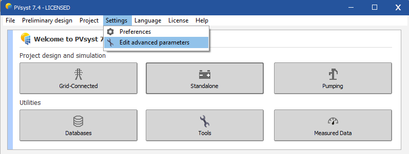
Dear Swonno, You can modify the limit parameter to allow PVsyst to run the simulation. Got to "Settings-Edit advanced parameters" In the search box, type "inverter" and find the line "The Inverter power is strongly oversized." Adjust the ratio to, for example, 0.1 as follows: This will enable you to run your simulation. Don’t hesitate to reach out to us if you have any questions. Regards, Muhammed Sarikaya
-
Dear Swonno, From SketchUp, it's important to assign a material to the surface of the PV module. You can also assign a material named 'ground' to it in SketchUp. Then, when you import into PVsyst, you must define what is a PV object by checking the box corresponding to the material name, and what is a terrain object by selecting the box with the associated name. I invite you to read our tutorial on this topic. Here's how you can find it: Regards, Muhammed Sarikaya
-
Dear Valerie Unfortenately it's not possible to do this. Regards, Muhammed Sarikaya
-
Dear Aidenn, It's likely because you forgot to enable an option in PVcase. You need to import the PVcase layout with the 'Terrain-following trackers' option enabled. This will break the layout into smaller trackers for PVsyst to account for motor and joint gaps. You should consult the PVcase help section and search for 'TFT' to find the procedure to follow. Regards, Muhammed Sarikaya
-
First of all, I need to understand whether you have a PV table or just a single PV module. Could you please share your DAE file with us at support@pvsyst.com for further investigation? This will help us identify where the issues are. Regards,
-
Dear Jig, I invite you to read about the topic of albedo at: https://www.pvsyst.com/help/albedo.htm And about the topic of soiling at: https://www.pvsyst.com/help/soiling_loss.htm Regards, Muhammed Sarikaya
-
Dear Loïs, I invite you to read the FAQ section regarding this question: Regards, Muhammed Sarikaya
-
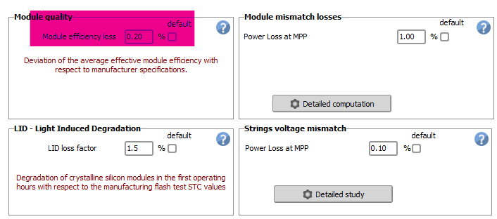
Dear Aidenn, For this value, leave the module quality box checked to use the manufacturer's specifications. Then, the three other values will never appear on the datasheet. It depends on your decision. Please click on the question mark next to each definition for more information. Regards, Muhammed Sarikaya
-
Dear Abeer, Your simulation may not perform well. It would be better to place the PV table above the topography. Regards, Muhammed Sarikaya
-
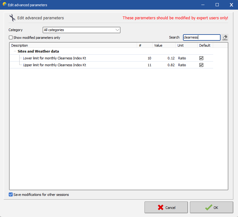
Dear Jonasf, I don't understand "simulate failure of a device." What do you mean by this? Indeed, for a standalone project, there is no "unavailability period." You can't import a custom Earray into PVsyst; the software is based on weather data and calculates from this with PV modules. When importing weather data into PVsyst, the software controls it to check if it is realistic or not. This is why you get the error message. It's possible to modify some advanced parameters for limit conditions like what you are trying to do. Go to "Settings - Edit Advanced Parameters." Then, put "clearness" in the search box. You will see two limit parameters that you can modify. Try to decrease the first parameter and increase the second. Tell me if you succeed and don't hesitate to reach out to us for more precision. Regards, Muhammed Sarikaya
-
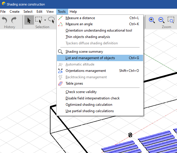
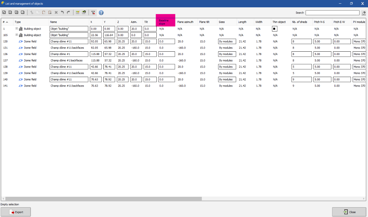
Dear Abeer, I invite you to watch this tutorial for a more detailed explanation: There is a workaround: in the shading window, go to "Tools > List and Management of Objects." Then, change all the baseline slopes to 0, as shown below: However, your PV array will not automatically adjust to the terrain; they will all have different heights. Try this and let me know if you succeed. Regards, Muhammed Sarikaya
-
Dear Meurville, What is the purpose of restricting the inverter? Can you explain exactly what you want to do? Regards, Muhammed Sarikaya