laurahin
-
Posts
76 -
Joined
-
Last visited
Everything posted by laurahin
-
Near Shading Losses Vertical E/W system
laurahin replied to RobertH's topic in Shadings and tracking
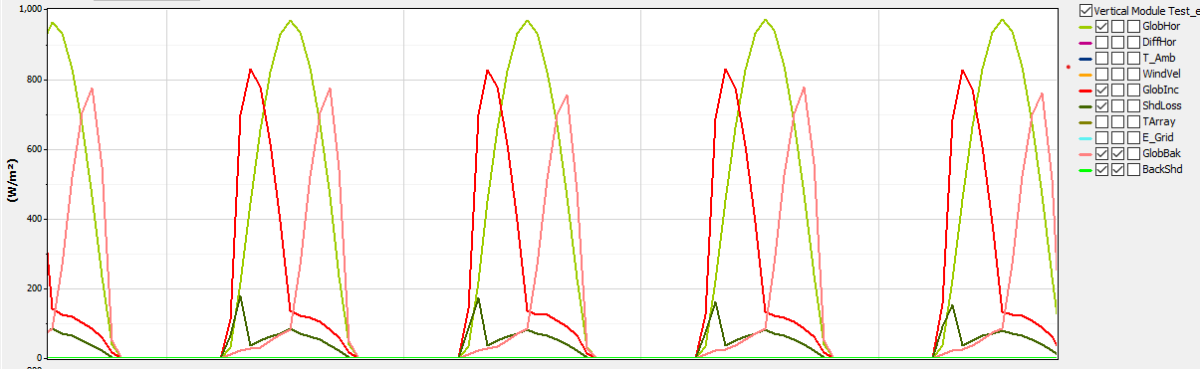
As a follow-up question regarding bifacial modules in a vertical orientation: Will PVsyst eventually know to treat a vertical bifacial module as having two "front" sides, such that near shading is computed for both sides? In recent tests, I found that the only shading I could put on the back side of the module came from the standard bifacial setting "rear shading." If I set this to zero, there is no near shading on the back side of the modules even though it occurs on the front. (This shading comes from the neighboring rows of modules, not shading objects.) Nevertheless, the "rear" POA irradiance is always lower than the front side irradiance, giving an asymmetry for front and rear irradiance, even on clear days. This I cannot explain. I do see that treatment of vertical modules is mentioned in the PVsyst v. 8 documentation, but it's not entirely clear what this will include. Modeling vertical module configurations seems to be an important development now. Thanks!
-
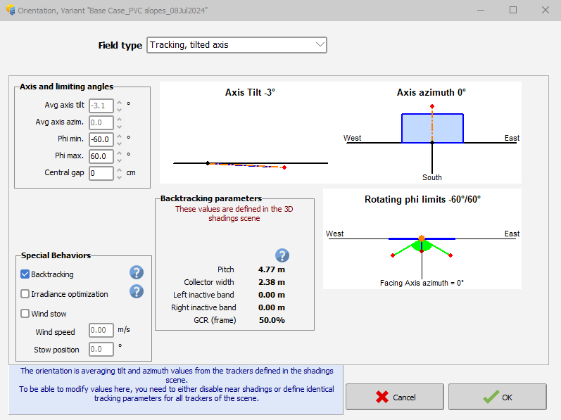
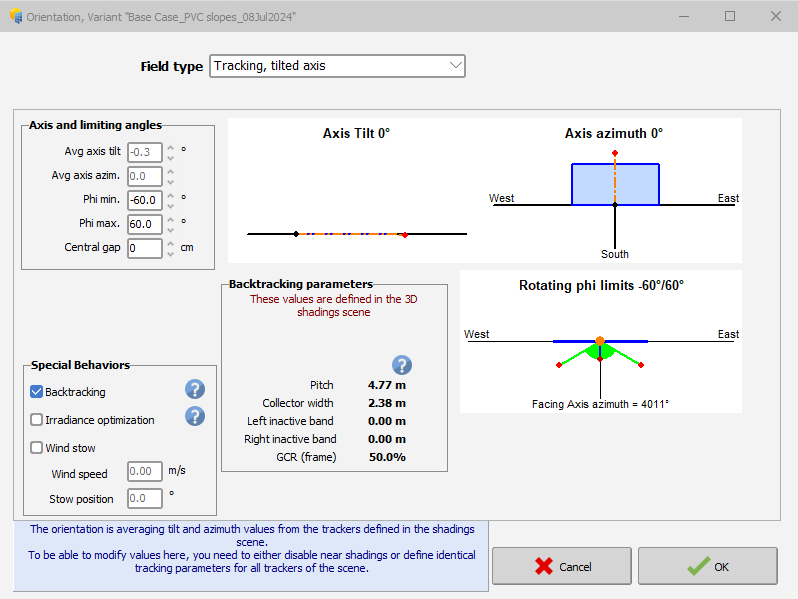
This turns out to be a "feature," not a bug: When you first open the project, PVsyst shows the tilt of the first tracker in the "Orientations" tab, but after you run the simulation, that value changes to the average. This was not the case in 7.3.
-
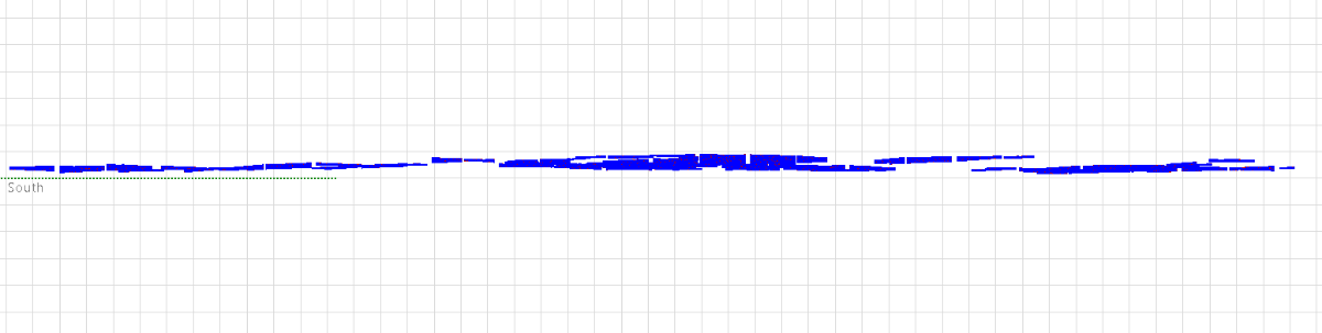
Hi, A colleague put together a shading scene using a PVcase pvc file that includes topography. When I open the project (after import), Orientation shows an average axis tilt of 3.1deg. My colleague's report shows 0.3deg. When I regenerate the report, it says 3.1deg, but when I rerun this variant, both Orientation and the report say 0.3deg. What's happening? Note that I have "Tracking: maximum axis tilt spread" set to 30deg and "Max. tilt axis for the Bifacial 2D model" set to 5deg; "Field type" is "Tracking, tilted axis." There is definitely N-S slope. In the image, one grid cell corresponds to about 72m. All runs give essentially the same energy output (within rounding error). First Orientation image is before run, second is after. Thanks, Laura H.
-
Help with error message for module "model is not yet computed"
laurahin replied to laurahin's topic in PV Components
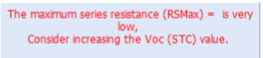
It turns out that these error messages don't appear until we select one of the graphs in the second illustration above, which is even more confusing. This all started because we get the following message when we first open the PAN in PVsyst. Perhaps this message should be in orange, not red, since the guidance is to "consider" a change and PVsyst will actually run. It was when we started to follow up on this message that the other errors appeared.
-
Hi, We got a new PAN file from a manufacturer, and after importing it, get the message "The model is not yet computed" under "Model summary" in the "Basic data" tab of the module info. The specific error is "Please define/check Rshunt and Rserie in the 'Model Parameters' tab." Given that Rshunt and Rserie have been supplied, I have to assume that the values break some rule in PVsyst, but we haven't been able to figure out what. The values _are_ a little strange: Rshunt = 12,000 and Rserie = 0.085. We're going back to the manufacturer for clarification, but if they stick with these values, is there any way we can get PVsyst to run, e.g., changing some hidden parameter? I can see a couple that might be relevant, but I don't know which is the right one or how dangerous the change might be. Thanks! Laura
-
I'm interested in calculating P-75, P-90, and P-99 values for PVsyst estimates. I looked at the help page on this subject (https://www.pvsyst.com/help/p50_p90evaluations.htm), and found that the only sources of uncertainty discussed in detail are related to input meteo data -- interannual variability, error in satellite data, etc. These are all things that the user can look up/calculate and apply to the PVsyst output themselves, externally to the PVsyst run. The part of the uncertainty that we're missing is that related to the PVsyst model itself. Could you supply some information about that? Clearly the full uncertainty is related to the quality of the inputs in addition to the uncertainty in model assumptions and algorithms, but it should be possible to estimate the magnitude of all of these effects independently (and I would hope that the uncertainty of the algorithms is checked every time an update is made, or there's no basis for making the update). In terms of the uncertainty of the inputs, you would just need to translate these uncertainties to the outputs, not estimate how bad people's input values are in the first place. Any information you could provide would be helpful. At the moment, IE's are guessing based on "experience" and comparisons to real systems, where errors in measured irradiance, deviation of construction from the engineering design, performance of trackers, etc., come into play. Thanks!
-
Recalculation of shading factors table required in batch mode?
laurahin replied to laurahin's topic in Problems / Bugs
Actually, the "diffuse integrals" are also being recomputed every time, regardless of whether I'm running a batch or not, apparently just because something changed somewhere in the configuration. I don't want that to happen either, because we are using all trackers in the diffuse shading calculation. Is there any reason we can't just be happy with the existing shading if the shading scene hasn't changed? -
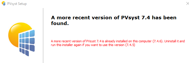
According to I should be able to install 7.4.5 while keeping 7.4.6. However, when I try installing 7.4.5, I get this message saying that I need to uninstall 7.4.6 first: What gives? I need 7.4.5 to update an older project and am not too excited about repeatedly installing and uninstalling different versions. Thanks, Laura H.
-
Hi, This might be considered a feature rather than a bug, but it's still a problem. I am rerunning a project in PVsyst 7.4.6 that had previously been run in 7.4.5. Despite the electrical loss/shading error in 7.4.5, this run remains our required reference. I would therefore like to keep the 7.4.5 shading scene that creates the electrical loss error. According to the version log, a change for 7.3.2 was Shadings: PVsyst now suggests recomputing shading factor tables if they have been computed with an older version and for 7.4.2 was Shadings: shading factor tables now remain valid if no changes have been made to the shading scene This does seem to be the case when I rerun the variant, but when I implement a batch run, the shading scene is immediately recalculated. Is there any way to stop this from happening? If not, this is a feature I'd like to see. Thanks, Laura H.
-
This is a known problem with v. 7.4.5 that has been corrected in 7.4.6. There should be many other posts on this topic on the forum.
-
I had this same problem with batch output files. There is data in every column A, but sometimes also in B or C.
-
Bummer. It seemed like a good idea at the time.
-
Could you explain what "Trackers with shadings: the partition model for electrical shading losses now considers the bottom row of cells" means? Thanks.
-
We haven't seen large changes in the electrical loss yet in our (admittedly limited) use of v. 7.4, which includes variants with significant terrain. Is it possible that the differences as great as 3% aren't attributable to the modified shading loss algorithms per se but to automatic selection of a different diffuse shading reference tracker when rerunning in the higher version? We definitely have seen elect. loss differences that great depending on the location of the reference tracker in an array.
-
Say you have an array with two different module types, same racking and orientation, but different module sizes. Is the difference in backtracking behavior caused by the modules having different lengths taken into account when transposition is calculated for this array? If it wasn't for the size difference/backtracking, the modules would all face the same way. Thanks!
-
If the answer to this problem is to turn the error off, why have the message at all? Maybe it should be a warning and not a prohibitive error? Laura H.
-
I looked at this help page from PVcase more closely. It appears that we have to run PVsyst twice if we want to get the electrical effects of shading correctly. Is that true? Thanks. Modeling Terrain following trackers from PVcase in PVsyst | PVcase Help Center
-
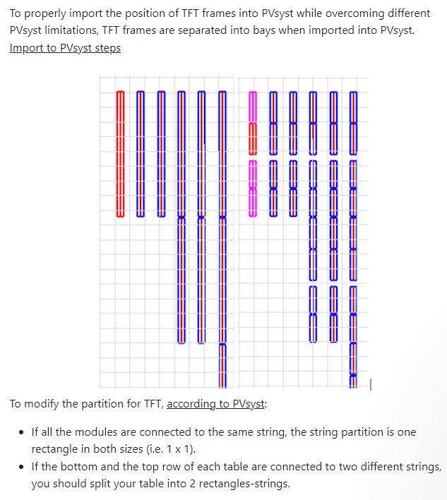
Hi, We are treating our first project that uses terrain following trackers (Nextracker XTR). When creating the scene in PVcase, our CAD worker had to define articulation points where the trackers could change angle. The design calls for 27 module strings, and they’re broken into groups of 6-8 modules as needed. During import into PVsyst, the tracker sections are being read in as separate trackers. We don’t have an issue with this, but haven’t found a way to define the partitions for electrical effect calculations. In the past, we have sometimes used slightly longer trackers in the shading scene to make them fit properly. In this case, we’ve used a non-integer number of partitions per object. We thought we would do the same here, but the non-integer values would have to be less than 1 and this isn’t allowed in the partition definition. Any recommendation? I saw some relevant info on PVcase’s web page (below), but didn’t understand it. It may be that we brought the scene in incorrectly (the “Import to PVsyst steps” link is broken) and the segments comprising each tracker are still associated in some way in their example. Thanks!
-
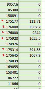
It is my understanding that if you enter a number of strings that isn't divisible by the number of inverters, PVsyst will find the correct configuration by varying the number of strings per inverter. Can you confirm that this means that the clipping will be different for inverters with different numbers of strings? I am finding that E out of the inverter may not be constant (the total AC capacity) at all times when there is (excess-power based) clipping. For example E out Clipped energy Presumably 176,000 kW is the nominal inverter capacity. Or could the difference be due to inverter derate due to heat or other factors? Thanks, Laura
-
Well, does each of the years use different met data? Or why are you doing a 20-year simulation?
-
PVsyst will not calculate like that. PVsyst will simulate the following: The reason for the difference between warning in one case and error in the other is that (for the warnings only) PVsyst in the first case does only a rough evaluation using the total Pnoms, it doesn't separate the two types of inverter. This seems to be a contradiction. How can PVsyst "only do a rough evaluation" in the first case when you say that it will separate out the inverters (86 with 21 strings, 14 with 22)?
-
Hi, We have just switched from v. 7.3.2 to 7.4.4. We like the new feature where PVsyst reads the correct inverter PNom limitation mode for power factor implementation, since we were checking and inputting this manually. We see that when we start a new project, the correct mode is shown and neither of the "PNom mode derogation" options is selected. However, when we load an existing project, there is always one selected. While we can then toggle back and forth between the two options, there doesn't seem to be any way to ask for the option to be automatically set based on the OND specs. That is, one or the other boxes will always be selected. Question: Is there a way to reset this selection? It might not matter, but giving someone an unneeded option is always leaving room for error. Thanks, Laura
-
My understanding was that this was explicitly against the PVsyst users license, but since they haven't commented....
-
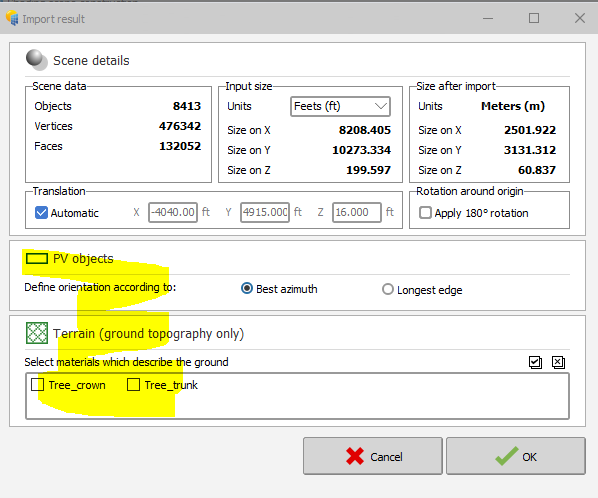
Hi, There are some new options when you import an external shading scene, such as from PVcase, and I can't find explicit documentation of them. 1) What does "best azimuth" mean in the "PV objects - Define orientation according to" setting, and how is it determined? 2) What does the "Terrain" option do? How would the tree crown "describe (maybe should be "define") the ground"? Incidentally, the plural of foot is feet. Feets is not a word in English.
-
This implies that users should bear in mind that the shading animation is only for educational purposes.
.png.6e5cb51c7af263e71cafb500f19a9e82.png)
.png.b99f79e6f2aae8dec0b0179bc7cff332.png)