All Activity
- Today
-
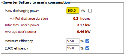
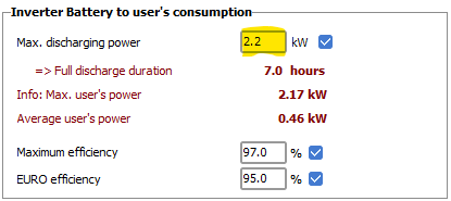
This concerns the inverter at the output of the battery pack. On the next page "Self consumption", please define the "Max. discharging power". As a first step, you can ask the default value proposed by PVsyst according to your consumption profile (checkbox on the right).

-
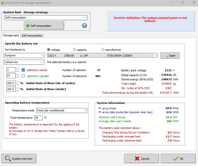
Hello everyone, When I enter the parameters for a self-consumption system with storage, an error appears that says: 'Inverter Definition: The output nominal power is not defined for a Sungrow battery with AC coupling.' I don't know what parameters I need to enter or where this parameter is located. Thanks in advance
-
In a project you can create multiple variants (both in version 7 and 8). Since the results will be for the complete system, you have to define your sub-system (for instance one inverter at the time) in separate variants. Thus, in the system window etc., define only 1 inverter and run the simulation. You can then make another variant of your project with the second inverter etc.
-
For your suggested workaround, how can I do that in PVsyst 7?
-
Hello, At the moment, PVsyst only provides yield and performance results for the complete system as a whole. Viewing results per inverter is not yet available (though it is on our roadmap). If you need results for each inverter separately, the current workaround is to simulate each inverter as its own variant.
-
Is there a way for me to view the result of a simulation per inverter stated in the System? For instance, the project has three inverters. I want to see the simulation result for each inverter that I placed in the csv file (time series data). Thank you.
-
 icicle joined the community
 - Yesterday
-
 Sunrays Energy LTD joined the community
 -
 Bengar9 joined the community
 -

PVSyst unexpectedly closes during long batch runs
Laurent C replied to Andrés Fernández's topic in Problems / Bugs
Dear Andrés Fernández, Please email us also at support@pvsyst.com : your PVsyst LOG files (using menu <File> <Export logs>) your project files (using PVsyst menu <Export projects>) so we can try to reproduce the issue you reported. Best regards. -
 rogoya7403 joined the community
 -
Thanks to this article I solved my problem.
-
 Christine Parr joined the community
 -
 Ecurepairtech joined the community
 -
OK, u are welcome
- Last week
-
 Mallex726 joined the community
 -

Backtracking Management Assistance Required
ASZulu replied to ASZulu's topic in Shadings and tracking
Hi Michele, 🙂. Thank you so much for the swift response. Yes, I was also confused by the same thing. I have shared the project file via email, as requested. Your assistance and guidance is really appreciated. -

Backtracking Management Assistance Required
Michele Oliosi replied to ASZulu's topic in Shadings and tracking
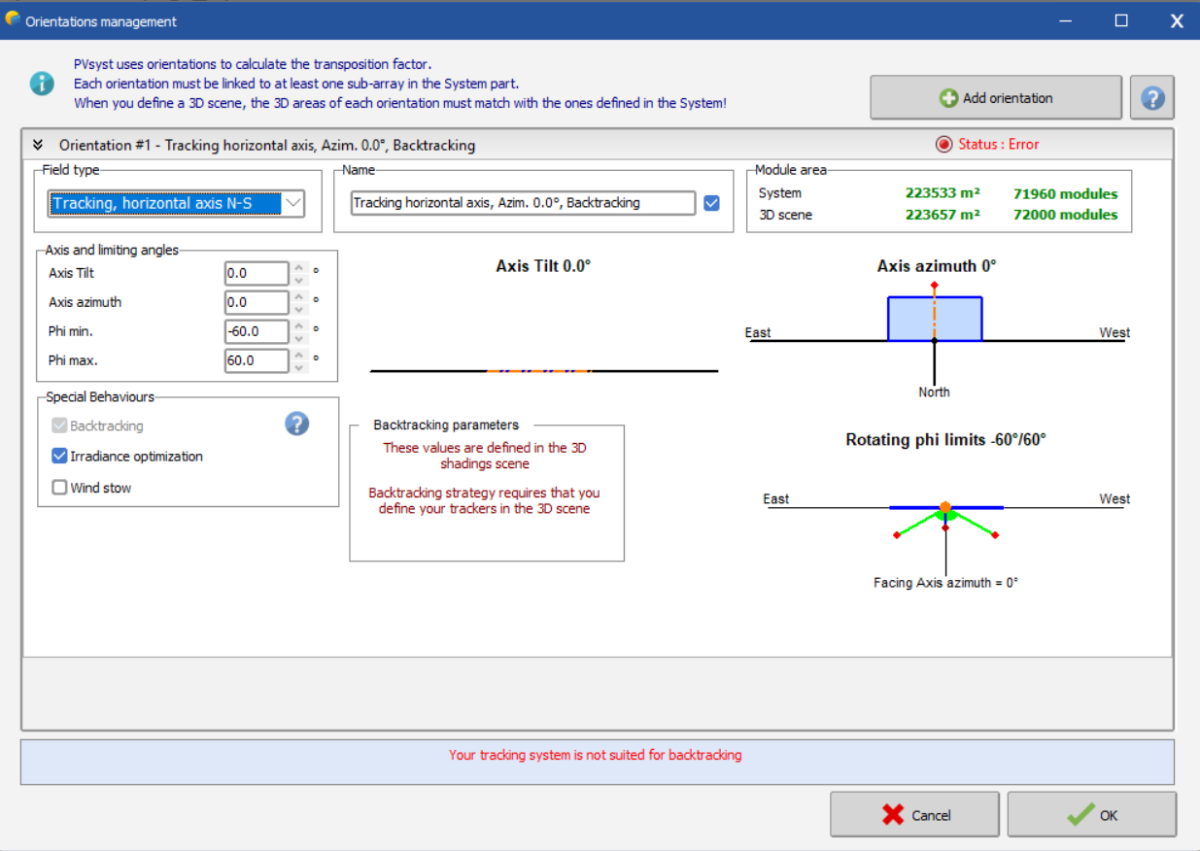
Hi, this is strange. NS axis trackers (whether 3D scene or using the “unlimited trackers” optimization) should work without issue. Can you send your project (use the export button in the project window to generate a zip archive with all necessary files) over to support@pvsyst.com ? Or share a snapshot of the disposition of your 3D scene. This will allow us to look into it further. -
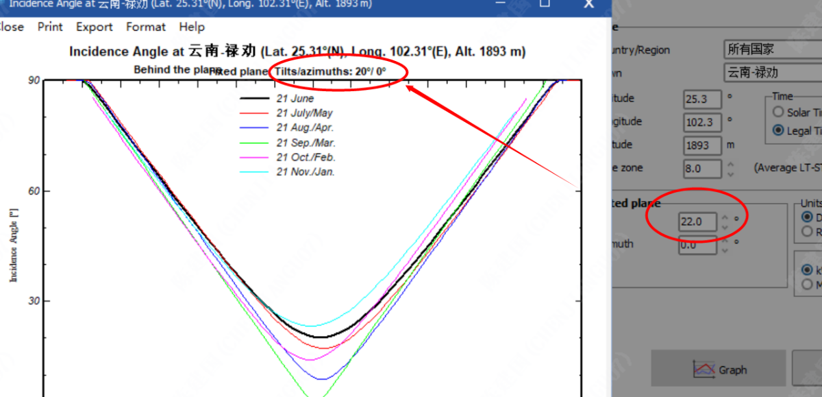
Yes sorry, this is an error in the graph title. The values for the curves calculation are indeed those specified in the dialog. Thank you for pointing this out. We will correct this for the next version 8.0.16.
-
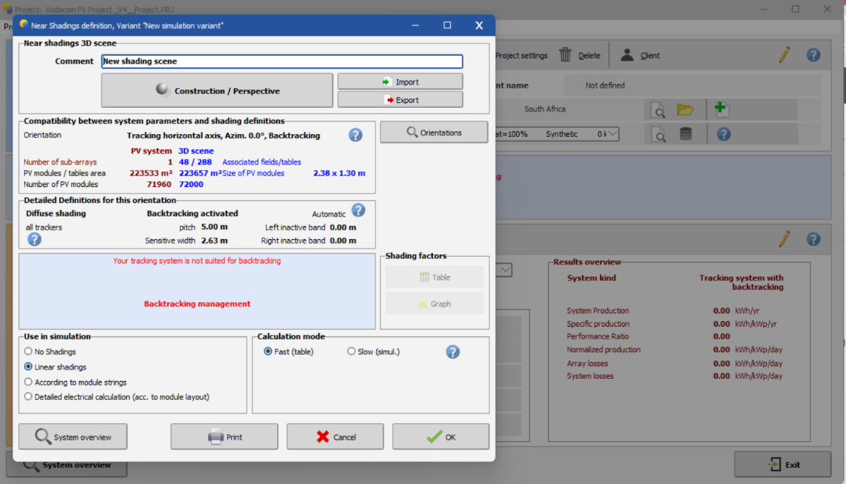
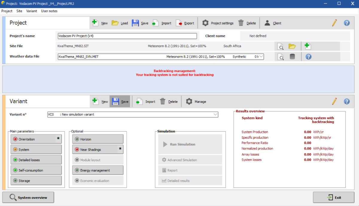
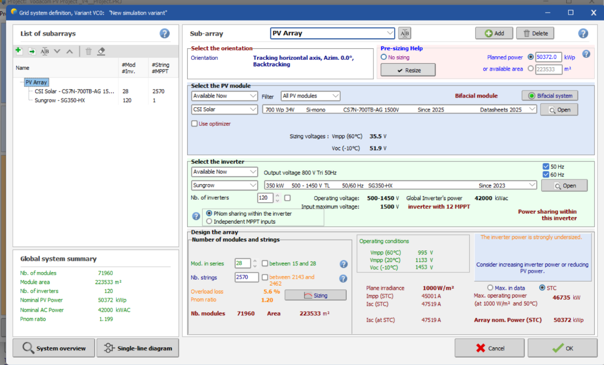
Hi everyone, 🙂! As a fairly new user of the software, I needed assistance with the Near Shadings for the simulation I am running. I keep getting the error stating "Backtracking Management: Your tracking system is not suited for backtracking" as shown below: Initially, I used "Unlimited Trackers with Backtracking" but noticed that PVsyst would not let me create a shading scene with this option/tacking system. This then resulted in the use of the tracking along the horizontal axis (with backtracking activated, and an azimuth of 0 degrees) as seen below. I am not sure how to proceed as the first screenshot above displays confirmation that backtracking has been activated from the "Backtracking Management" menu within "Near Shadings" and this is the only obstacle left before being allowed to run the errorless simulation. I have shared a screenshot of the System Overview below for context and convenience. Appreciate any and all help I can get on this. Thank you.
-
Dear sir: I found that the inclination angles of the two are not the same. Is it a bug?THANKS
-
ASZulu joined the community
-
Hi, The execution of the shading factor calculation may take some time, and has to be evaluated at each simulation hour. For speeding-up the simulation execution, we calculate a table of shading factors for specific sky orientations (every 10° in tilt and 20° in azimuth). Then at each step, the simulation can calculate the exact sun's position, and interpolate in this table ("Fast" shadings calculation"). This table is also used for the elaboration of the shading factor on diffuse and on albedo integrals. You find more details in our help, for instance the treatment of the Beam component: https://www.pvsyst.com/help/project-design/shadings/calculation-and-model/treatment-of-the-beam-component.html and the shading factor table: https://www.pvsyst.com/help/project-design/shadings/calculation-and-model/shading-factor-table.html Kind regards
-
 Dear Caio, Thank you for the suggestion. I will add it to our software development roadmap, but I can't guarantee when this feature will be implemented. Regards, Muhammed Sarikaya
 -
Is there a detailed guidance on the differences between the "fast (table)" option and the "slow simulation" option for the near shading? In order to understand possible deviance and what is best for the project. Thanks
-
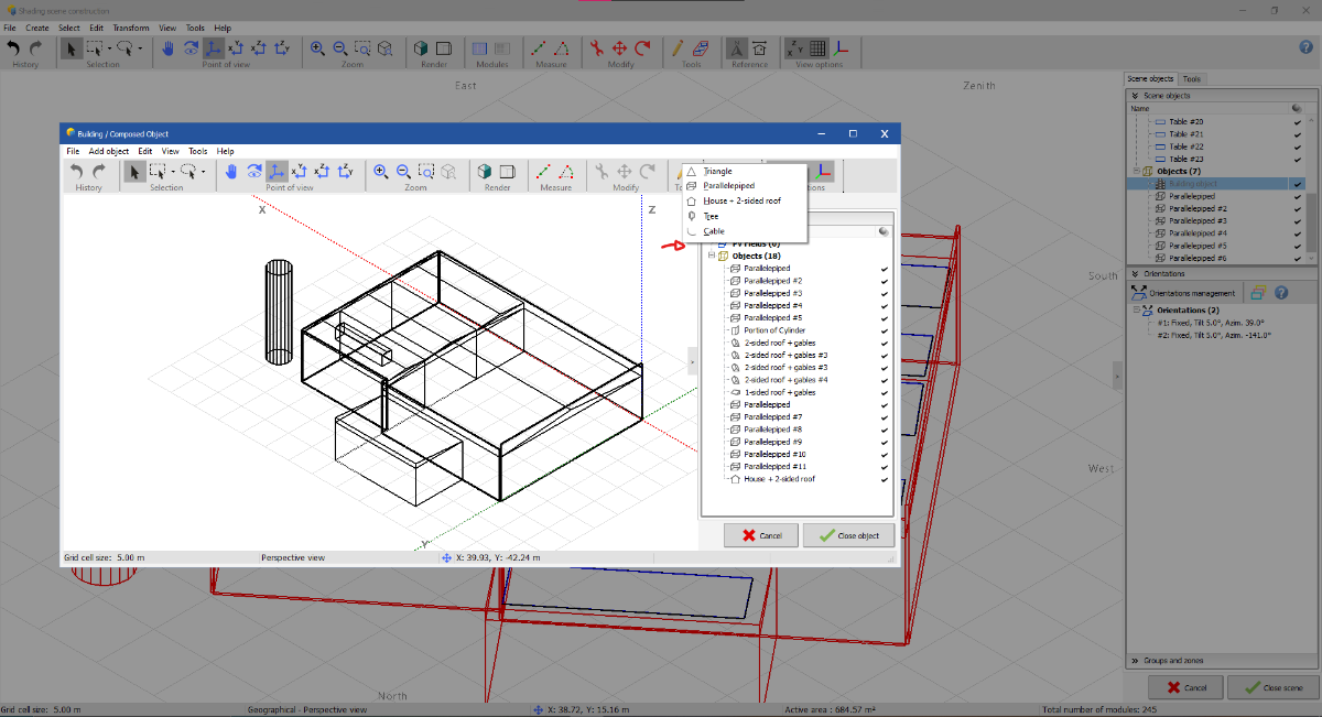
 Hi! Thanks for the feedback! In fact, PVSyst already has a free drawing tool. However, even in line with my feature suggestion, I believe an upgrade to this function is still needed. Currently, the standard tool in the software can only be activated in the standard Shading Scene Construction mode. In the Building Object mode, the “Pen – Extruded Polygon” option is not available.
-
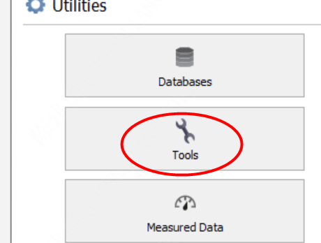
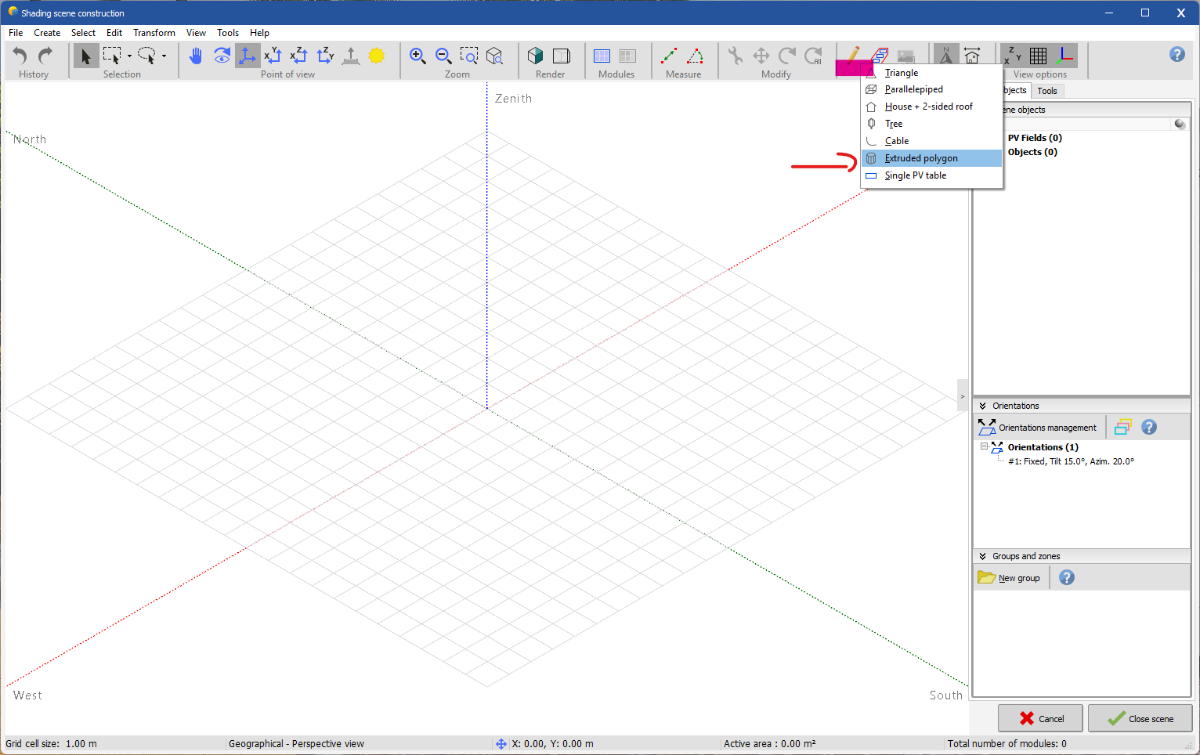
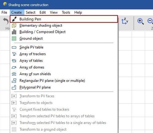
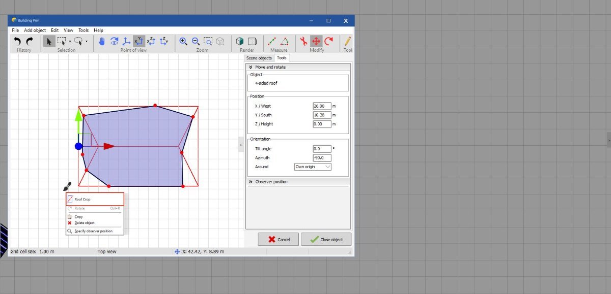
Dear Caio, Thank you for your suggestion to improve the 3D feature in PVsyst. For your first suggestion, I recommend trying the “Pen – Extruded polygon” tool (see below). It lets you draw a complex shape on the ground plane and extrude it to whatever height you need. Let me know if this helps. Regards, Muhammed Sarikaya
-
Report shows spectral correction applied even when it isn't
Michele Oliosi replied to LauraH's topic in Problems / Bugs
Indeed, I confirm that this is the case and is quite misleading… and also not consistent with how PVsyst usually works. You should not be able to keep the spectral correction checked if it cannot be used for some reason. Thanks for this feedback @LauraH -
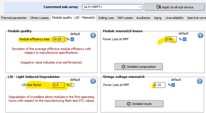
The "Module quality loss" represents the confidence you put yourself in the PV module real performance. See the help https://www.pvsyst.com/help/project-design/array-and-system-losses/module-quality-losses.html?h=module+quality The "Light induced degradation" affects only the P-type wafer-based cells. It is sometimes - rarely - mentioned on the datasheets. See the help https://www.pvsyst.com/help/project-design/array-and-system-losses/lid-loss.html?h=lid The "Module Mismatch loss" depends on the real module characteristics dispersion. See the Help https://www.pvsyst.com/help/project-design/array-and-system-losses/array-mismatch-losses/mismatch-loss-due-to-modules-dispersion.html?h=mismatch NB: you have little questionmarks buttons for getting help for each of these losses, please use them.
-
Hi PVSyst Team, Can we determine these parameters with the module info alone? I'm using Jinko Solar - JKM590N-72HL4-BDV and JKM595N-72HL4-BDV/ Please show how do we come up with the values. Appreciate your help, ~Aidenn
-
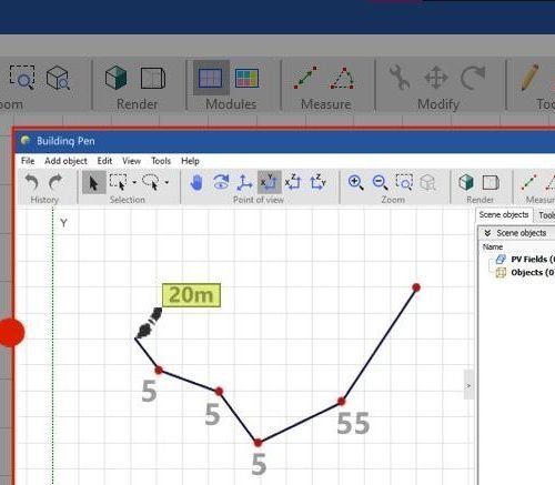
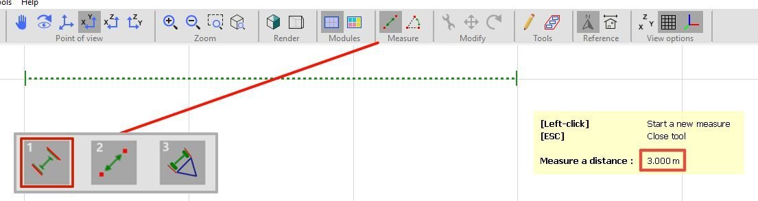
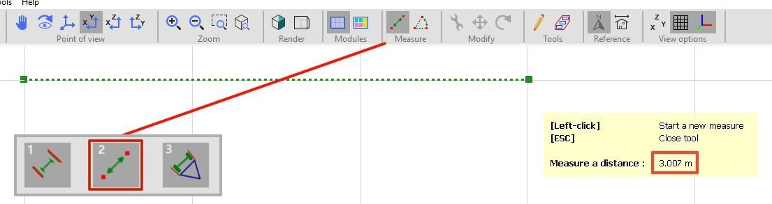
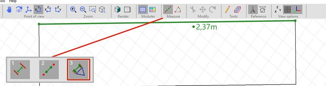
1 - Model Pen (Building Pen) The idea is to have a free-draw mode for creating complex or unusual building shapes, with the ability to adjust the height, length, and—if possible—the curve “resolution” (i.e., the number of lines used to form curves, similar to a cylinder’s segmentation). Ideally, this tool could be integrated into the Building / Composed Object section. Personally, I’ve found it difficult to create certain shapes and structures that could be done much faster with this improvement, especially roofs. Design Suggestion: Using software like SketchUp or SolarEdge makes this process easier because they include a pen tool and are not limited to predefined models, allowing for more flexible scene composition. If this feature were implemented—considering any software limitations—it would be extremely useful to combine it with the ability to configure any roof shape based on a drawn outline, merging the best features from other tools in one place. Design Example: This tool could work in two alternative ways: Building/Object Pen – Functions like a freehand pen to draw custom shapes. Building/Object Cropper – Used only to cut or reshape predefined objects/buildings into the desired form (simpler from a general perspective). 2 - Magnetic Measure Mode This idea is much simpler than the previous one 😄. The goal is to customize the measurement tool to work faster and more accurately in determining dimensions. It could have three modes: 1. Full Magnetic Measure (Grid-Based) – Snaps measurements to whole number values (e.g., 1m, 24m, 87m). 2. No Magnetic Measure (Standard) – Works as the current free measurement tool. 3. Full Magnetic Measure (Object-Based) – Click any object edge/line to automatically display its length. That’s all for now. I’ll be back with more ideas and suggestions. I really enjoy using this software and wish the best to its developers. Thanks for your attention!
-
Caio Almeida joined the community
-
 nyasha Mukosi joined the community
 - Earlier
-
 By default we recommend Uv=0 as this coefficient is trickier to measure and varies even more from one PV installation to the next. There can be a large difference between the wind speed from a data provider (measured at 10m above ground, not always close by) and local conditions at the module level. But yes to be more accurate you simply need to measure this coefficients on your installation. https://www.pvsyst.com/help/project-design/array-and-system-losses/array-thermal-losses
 -

In-depth Inquiry on BIPV Aging, Temperature Modeling, and Loss Equations
Zahra replied to Zahra's topic in Meteo data
Thanks for respond, How about Uv? is there anyway to model it more accurate?