All Activity
- Past hour
-
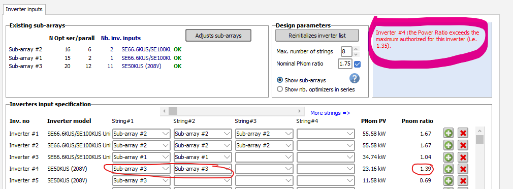
We are using the SE50KUS (208V) inverter. Getting an error when i assign 2 strings (1.39DC/AC) ratio to it. Error says i cant go over 1.35 dc/ac ration. this does not seem right and i cant find out how to change it.

- Today
-
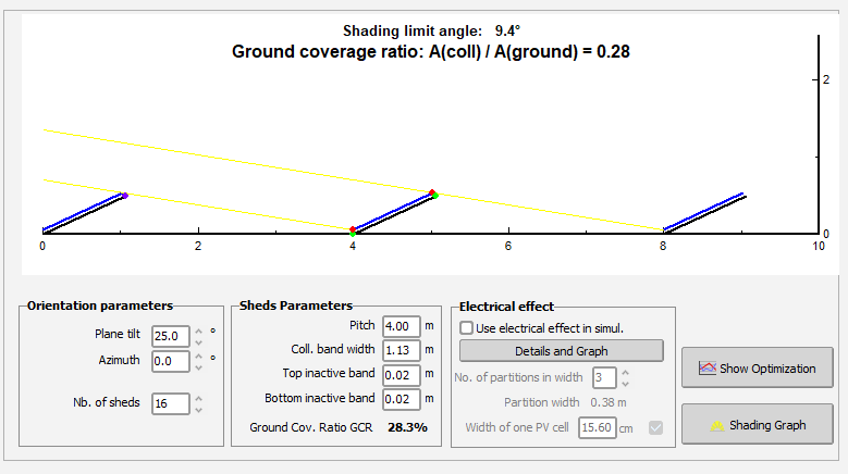
@AHSAN ALI An important point here is understanding what "shed" means. A "shed" in PVsyst is one row of PV tables in a row arrangement. A "shed" is not the same as a module: Because one table may have several PV modules. Because one row of tables has several tables in it. In the diagram of the "Orientation" window, you can see three (generally) such rows depicted in blue. This is a cross-section or side view of the row arrangement. This also means that the size of the tables is what you will enter in the parameters "coll. band width" and "top/bottom inactive bands". What matters is the vertical size, in other words the "height" or "width" depending on your perspective, but usually the short side of a table. The "Orientation" window is not where you will define the total number of modules. Here only the geometry matters. The "System" window is where you will define the number of modules properly. In your example with 8 + 8 modules, you should define "Nb. of sheds" as 2.
-

Modeling losses when Vmp is lower than the MPPT range
Michele Oliosi replied to Shwetha Vara's topic in Simulations
Hi, PVsyst will use the operating range to displace the operating point on the IV curve. This displacement away from the MPP will cause losses, captured in the variables IL_..., e.g. IL_Vmax for the maximum voltage. The parameters here are the Vmax and Vmin parameters. Note that a different yet related loss, the derate at very high or low voltage levels (or more generally as a function of voltage), is not captured by PVsyst. We do only model a voltage dependence by means of three caracteristic efficiency curves based on three ordinary voltage points. However this may not capture the full voltage derating curve. -
Bonjour, Pour toute demande relative à la gestion de vos licences, nous vous invitons à contacter le support PVsyst via le formulaire dédié : https://www.pvsyst.com/fr/support/contact/activation-problem/ Cordialement.
-
 saleh joined the community
 - Yesterday
-
Can we simulate in unlimited sheds orientation, elevated structures or ground mounted only, but if ground mounted only then can we simulate L2,L3 structure in this, because in orientation we can only give pitch, collect band width (What is this?). No of Sheds also, but If I've a wide roof can I only install a single panel in unlimited rows I can select panels in front row more than one and also behind the rows then how to calculate or simulate, shading angle, collec band width etc.I can't understand bcz I want to install a 10kW system of 645W panel, but I give 16 no of sheds bcz of unlimited sheds, how can I reduce the qty of sheds bcz I want to install 8 panels in 1st row and 8 in 2nd and that's all, but how will manage
-
 Is there any change required in the PAN file if we change the Solar Cell ? If yes then what are the changes required? What are the changes in the PAN file required if we are changing the Cell Dimensions but the same technology.
 -
 Fedile joined the community
 -
 JOMINJU joined the community
 - Last week
-
Não existe campo de eficiência do módulo. Falta informação nos datasheet para preencher os formulário. Existe um modo de importar os dados do módulo diretamente do fabricante?
-
 CLIMAR LOPES DA SILVA joined the community
 -
Bonjour j'ai un problème d'activer la licence pvsyst 7Pvsyst 7.0 Merci cordialement
-
 Ousmane Drameé joined the community
 -

PVsyst v6: Inconsistent Date Format in Hourly Output .CSV File
kjs55 replied to kjs55's topic in Problems / Bugs
None of the methods proposed thus far in this thread work for me over the entire PVsyst date column. You can see the problem if you open the PVsyst output CSV file in Excel and add a new column with the formula =DAY(PVsyst_date) and drag it down. The root problem is that the PVsyst output date column contains mixed data types/formats (both serial numbers and text strings). Here is what I finally found to work for the default PVsyst output date format "DD/MM/YY; Hour; (Excel)": year =IF(ISNUMBER(PVsyst_date+0),YEAR(INT(PVsyst_date+0)),1900+VALUE(MID(TRIM(PVsyst_date),7,2))) month =IF(ISNUMBER(PVsyst_date+0),DAY(INT(PVsyst_date+0)),VALUE(MID(TRIM(PVsyst_date),4,2))) day =IF(ISNUMBER(PVsyst_date+0),MONTH(INT(PVsyst_date+0)),VALUE(LEFT(TRIM(PVsyst_date),2))) hour =IF(ISNUMBER(PVsyst_date+0),QUOTIENT(ROUND(MOD(PVsyst_date+0,1)*1440,0),60),VALUE(MID(TRIM(PVsyst_date),10,2))) minute =IF(ISNUMBER(PVsyst_date+0),MOD(ROUND(MOD(PVsyst_date+0,1)*1440,0),60),VALUE(RIGHT(TRIM(PVsyst_date),2))) second =IF(ISNUMBER(PVsyst_date+0),MOD(ROUND(MOD(PVsyst_date+0,1)*86400,0),60),0) xlsdatenum =DATE(year,month,day) + TIME(hour,minute,second) -

New tool Shading scene (ground objects)
LauraH replied to Barbadori's topic in Shadings and tracking
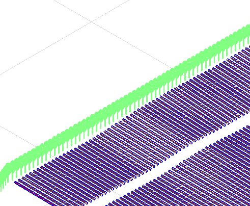
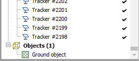
I received a shading scene in which all of the trees are included as a single ground object. This seems like an incredible way to represent many trees as one object. They do seem to throw shade. Q: If trees shouldn't be included in the ground objects, why are those options given for a PVC import? It looks like the tops of the trees will be considered the ground if you select the first box. Nevertheless, individual trees are depicted in the shading scene. Second screen shot shows that no trees are included in the object list. Thanks.
-
How does PVsyst account for losses when the temperature-adjusted Vmp of the panels falls outside the microinverter’s MPPT operating range? What is the typical impact on power production accuracy in such cases? Which inverter parameters in PVsyst can be adjusted to model the power reduction accurately when this condition occurs, ensuring the losses are properly represented?
-
 Shwetha Vara joined the community
 -
Yes that is correct
-
That's an interesting approach but I am surprised by the mismatch. It looks to me like the RPOA (darker curve?) was measured on a tracker and the fitted ones (brighter red?) are done for a fixed tilt setup. Or one is backtracking and the other is not? Maybe cross check the tracker definition in the bifacial window. If you have a complex setup, make sure the parameters here match the one tracker your RPOA measurement is installed on.
-
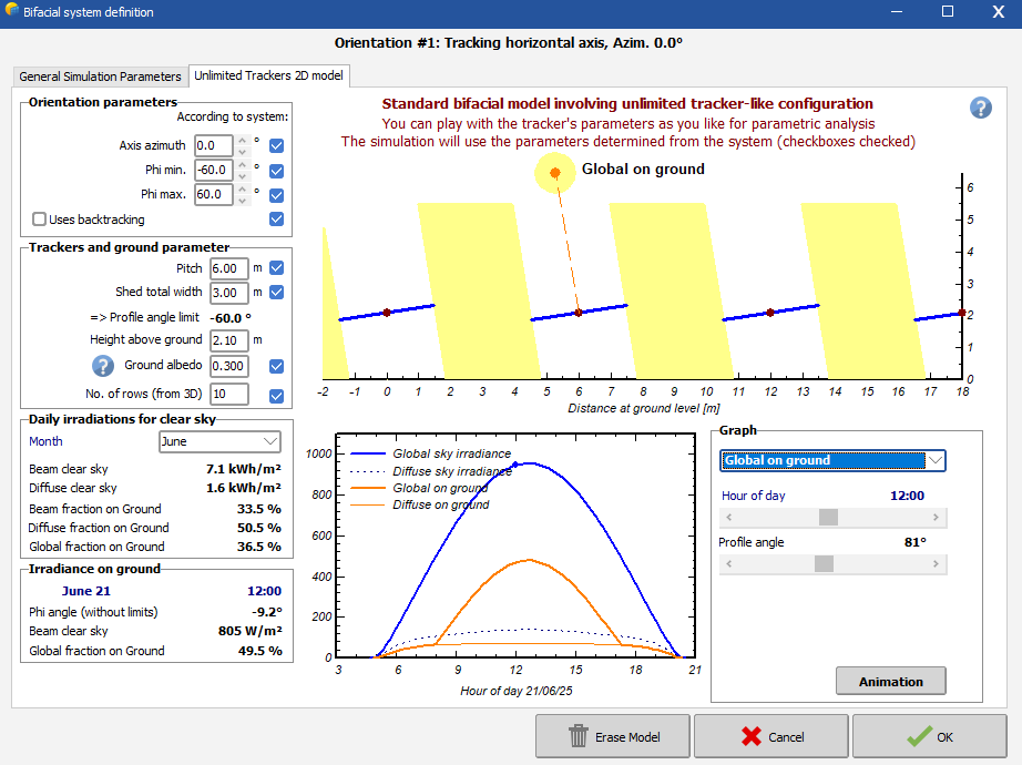
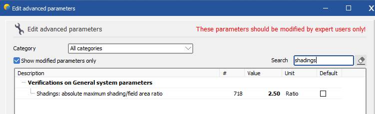
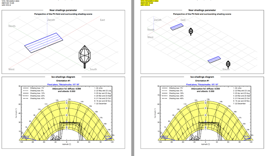
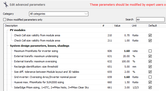
Indeed, the bifacial calculation in PVsyst is based on a 2 dimensional representation for regular system layout, thus same orientation, table size and pitch, to calculate how much irradiance is falling between the tables and how much will be scattered up on the back side. You can define individual orientations for each table. Though, since you need a pitch it is not yet possible to simulate a bifacial system with a single row. A possible workaround is therefor to duplicate your 3D scene so that PVsyst can detect a pitch, similar to the example below: Verify that the tables are well aligned so that indeed PVsyst detects the pitch in bifacial window. Note that the amount of tables in the 3D scene will be double what you have defined in the system and this will create a warning. You can increase this limit in the advanced parameters. In the first PVsyst welcome window, click “Settings” and “Edit advanced Parameters” and find the parameter that triggers the error message – “Shadings: absolute maximum shading/field area ratio”. This will allow you to run the simulation Kind regards
-
If the sensor(s) is in front of the torque tube and other items, (GlobBak+BackShd) * 𝜑 is sometimes used. Install sensors midpoint between two piles for tracker systems.
-
 Alpha joined the community
 -
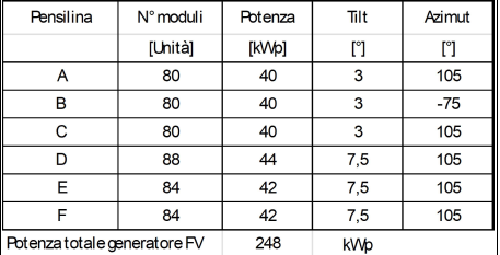
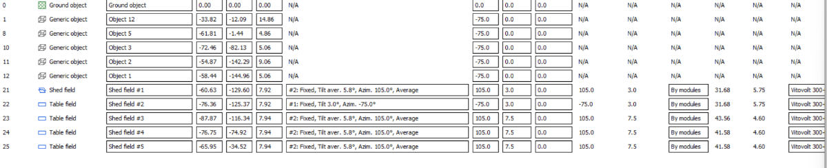
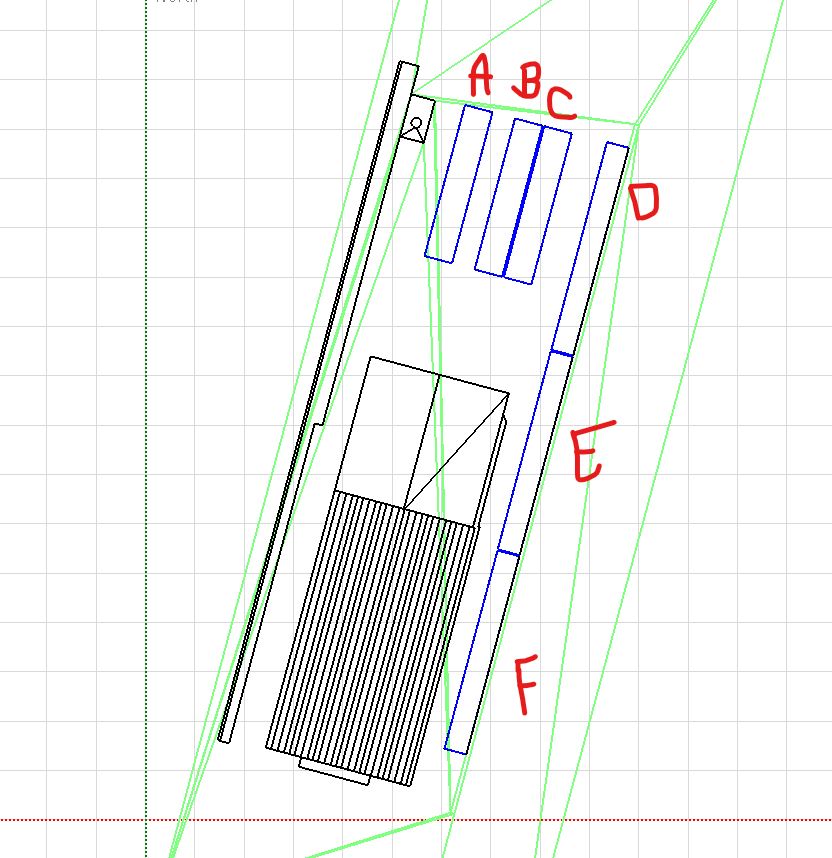
Good evening, I've to run a simulation of a small PV plant, 248 kWp, with modules placed over carports. I've 6 carports in total, but just two (A and C) have the same tilt and Azimuth, you can observe this point by this table: Modules will be placed with a 5Landscape arrangement over carport A, B, C, and with a 4L arrangement over carport D, E, F. I really need to consider bifaciality contribution in the simulation, but this is seems not to be allowed because i've single tables and not an array of tables, aswell seems not to be allowed because i've 4L configuration on some tables and 5L on other ones. I tried to set carport's tilt and azimuth (for B-D-E-F) as average, but this didn't solve the problem. Is there any way to consider bifaciality in that type of configuration. I kindly ask for a suggestion, best regards, Stefano Martini (project engineer for Gruppo Undo)
-

distance from ground - zone in PVsyst shading scene
Linda Thoren replied to PVsystUser's topic in How-to
With PVsyst version 7, it was an automatic mode for diffuse shading calculations for systems that involve trackers, in version 8 the automatic mode has been removed. Now, users are required to manually define a representative tracker for diffuse shading calculations. You define a representative tracker by clicking “Tools”, “Trackers diffuse shading definition”. In this tool you can choose to calculate the diffuse shading factor for all trackers, or select a representative tracker that will be used to evaluate the diffuse shading factors You can find more details about this update and instructions in the PVsyst Help documentation here: PVsyst Diffuse Losses with Tracking Systems. Indeed, many updates and improvements has been done since version 7.2.16 that especially concerning the near shadings. In general you can find the changes that has been done in the release notes and major changes are discussed in the forum in the links below: https://www.pvsyst.com/help/release-notes/index.html#exec-1--version-801 https://forum.pvsyst.com/forum/29-pvsyst-main-changes/ -
 Stefano Martini joined the community
 -
Continuing the question: I am thinking about 1 - ignoring this shape difference and count it as uncertainty, or 2 - Consider the module as monofacial, and "boost" GPOA values with the mantioned formula: E_Total = E_POA + E_Rear * 𝜑 or E_rear = RPOA * (1 - "Structural shading factor") The second option makes sense? If so, which formula would be more accurate? Thanks! Rafael
-
That's a very interesting topic! I am also carrying out a performance analysis, with RPOA measurement... Since it is not possible to use it on the .MET file (like GPOA), I am trying to fit the bifacial parameters (structure shading + transparent fraction) running multiple simulations and comparing the results (GlobBak) to the measured GPOA, to see which one fits best. Apart from the absolute values, all simulations showed the shape curve similar to GHI, while the measured curve showed a shape similar do GPOA: Is this have something to do with the assumption that the re-emitted irradiance is isotropic? This text below was taken from PVsyst help: Or am I doing something incorrect? Maybe "Globak" is not the right variable to compare with RPOA? Even so, would the shape of the curves would be that different? Best regards, Rafael
-
Thanks
-

distance from ground - zone in PVsyst shading scene
PVsystUser replied to PVsystUser's topic in How-to
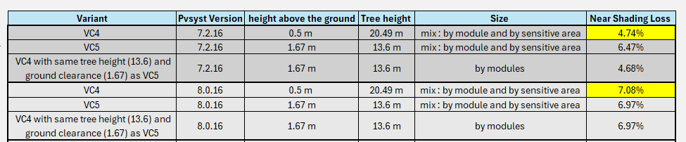
I ran the same variant in PVsyst 8 and got a huge difference in near shading loss. Does it make sense? please see the highlighted cells below. the only difference between two is they were ran in two different versions:
-
 Kareem Shaaban Ragab joined the community
 -
distance from ground - zone in PVsyst shading scene
PVsystUser replied to PVsystUser's topic in How-to
Thanks but there is no such thing in V 7.2.16 -
Thank you Auriane - just to ensure that I have this correct, it's best to apply the rear-side structural shading factor to the measured RPOA because it is most important is to account for the light that is realistically reaching the rear side of the modules? This equation for E_rear would look something like the following using the measured RPOA... E_rear = RPOA * (1 - "Structural shading factor") So, please correct me if I'm wrong, but it sounds like it's accurate to say that GlobBak is not by itself analogous to measured RPOA because it has been reduced by a structural shading factor, where an unobstructed RPOA pyranometer would not be. I understand that what's most accurate may be to calculate the incident irradiance on the rear side of the module, but in my experience many engineers desire to modify measured sensor values as little as possible. In such a case, would it be more analogous to combine GlobBak + BackShd so that in the performance analysis both E_rear terms reflect the rear side irradiance before being reduced by the shading factor?
-
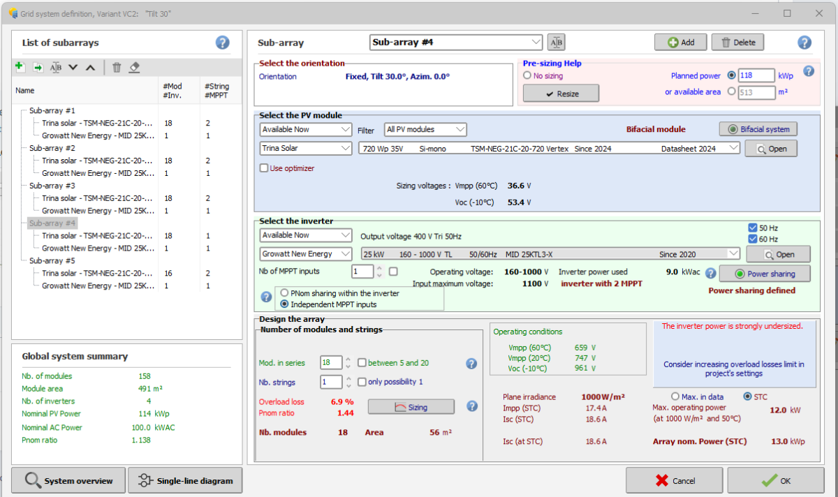
Inverter Power Strongly Undersized Error Message is not cleared
Linda Thoren replied to NavidSa's topic in Problems / Bugs
Hello, This limit that the error message is referring to is in the Project setting, not the advanced parameters. Kind regards -
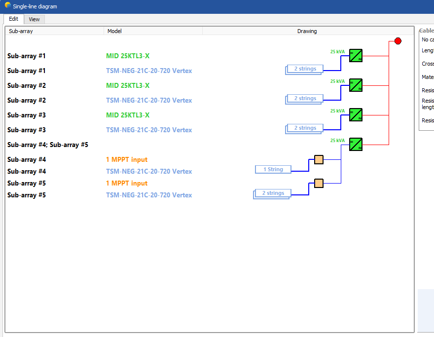
 Hello, I have a problem in a grid connected project by 25kW MID 25KTL3-X inverter. It's my pleasure if anybody can kindly help. I selected Trina solar 720Wp Panel for my project then I tried to connect one 18 modules string to one MPPT input and 2x16 modules str ings to the other MPPT input. Although I changed the limits of PnomRatio and Oversizing array/inverter nominal power to 1.6 or even 2 the "inverter power strongly undersized" error message is still not cleared and I can not go to simulation step.