Search the Community
Showing results for tags 'bifacial'.
-
Pertaining to capacity or PR testing, the following equation is frequently referenced for total irradiance calculations: E_Total = E_POA + E_Rear * 𝜑 ...where 𝜑 is equal to the module bifaciality factor. My question concerns the E_Rear term: if a PV system has a pyranometer installed in the rear plane of array in such a way that it is unobstructed by structures such as the torque tube, and the E_Rear used for the physical PV system is the measured RPOA from this pyranometer, what do you recommend using for the E_Rear term to calculate an equivalent model-side E_Total? Would the E_Rear term be the output variable GlobBak, a combination of factors such as GlobBak + BackShd, or something else? Reference: Waters, Martin, Chris Deline, Johan Kemnitz, and Jeffrey Webber. 2019. Suggested Modifications for Bifacial Capacity Testing: Preprint. Golden, CO: National Renewable Energy Laboratory. NREL/ CP-5K00-73982. https://www.nrel.gov/docs/fy20osti/73982.pdf
- 8 replies
-
- irradiance
- rpoa
-
(and 5 more)
Tagged with:
-
Greetings PVsyst team. I'm working with a PV system with bifacial and monofacial modules. I've already created differents orientations for each sub-array, but now I wonder how PVsyst consideres theses two kind of modules on simulation. There is any other parameter I should keep my eye on it? In future versions, would be possible to set degradations per sub-array?
-
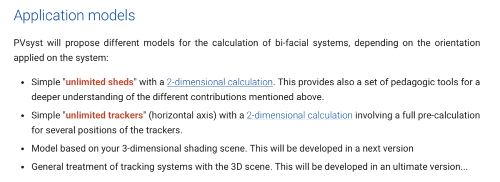
Hi, for bifacial systems, is it possible to use Unlimited Sheds in the 3D scene? Also, when I use Fixed Tilt, I get results very similar to monofacial systems. Does this mean Fixed Tilt is not suitable for bifacial systems? The information provided suggests using Unlimited Sheds or trackers-does that mean Fixed Tilt doesn't properly account for bifacial gains?
-
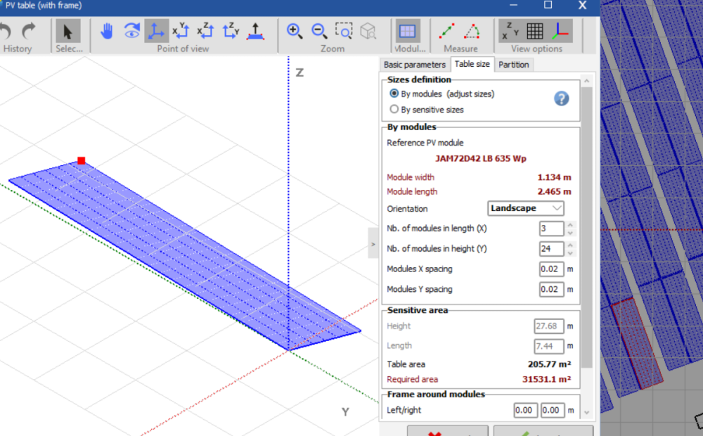
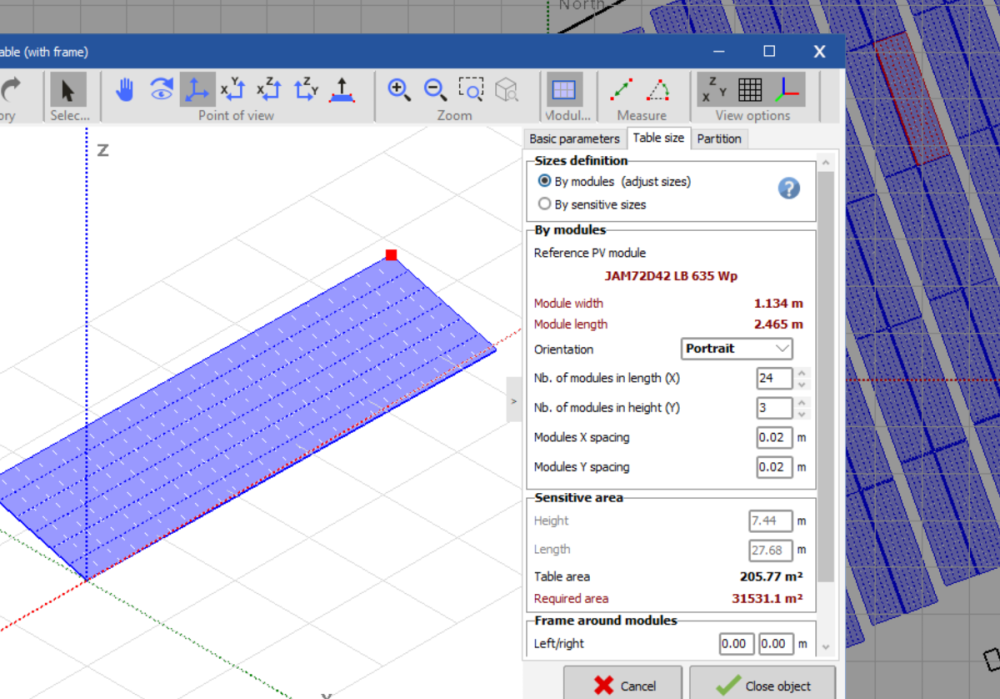
Hello, When I import a scene from PVcase, in several occasions the tables take two different orientations automatically, either modules in portrait (3 rows x 24 modules) or modules in landscape (24 rows x 3 modules). This was not a major issue in PVcase 7 as in the orientation manager you could override this. However, in the new PVsyst 8, with and EW system I can not simulate the bifacial option as the widths of the tables are not the same (an error pops up). If I change manually in the list of objects the configuration of these "wrong" tables, they move all over the scene. How can I fix the error in importing/reading correctly the tables? This would also reduce the threshold of the setting in max. spread of azimut for the same orientation. Note: this is not an issue of this particular project as it has happened before in multiple projects. Many thanks!
- 1 reply
-
- pvcase
- orientation
-
(and 4 more)
Tagged with:
-
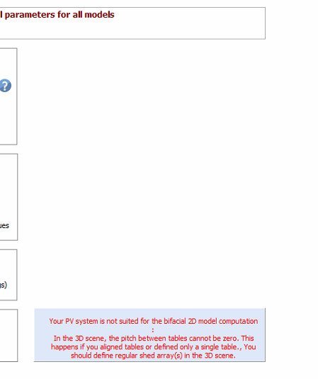
Dear all, I would like to ask how to simulate a solar fence with bifacial panels. In the "Near Shading" I drew several tables for the solar fence elements. But now in "System" - "Bifacial system" settings, I see an error message: "Your PV system is not suited for the bifacial 2D model computation. In the 3D scene, the pitch between tables cannot be zero. This happens if you aligned tables or defined only a single table. You should define regular shed array(s) in the 3D scene." For a solar fence I don't need a pitch. Is there a way to solve this? Thanks for the support. Best regards, Rebecca
-
I have a project where I was asked to add a geo membrane to improve Albedo. The supplier gave me the Albedo value for the membrane but also gave me the annual degradation values for the material reflectivity. I wanted to run a batch simulation where i change the Albedo with the years but i can't find this option. Is there another way to do it?
-
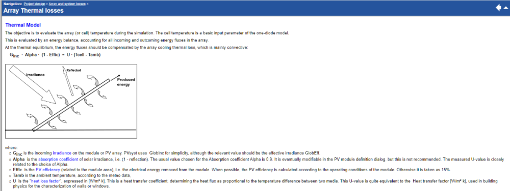
How are thermal losses accounted for in bifacial modeling. With surfaces that have a high albedo, do thermal losses from the heat due to the reflected light become a factor? If not what is a appropriate way to use PVsyst to model that type of effect. I attached a screen shot from the PVsyst documentation for reference. Thanks in advance!
-
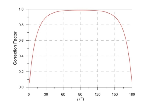
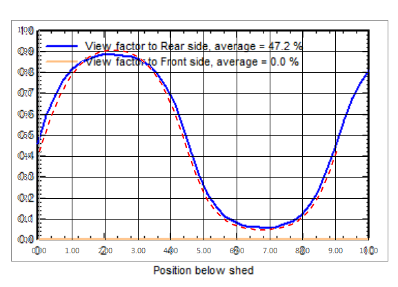
Hi, I've been comparing the rear irradiance model published by Marion et al. ("A Practical Irradiance Model for Bifacial PV Modules", 2017) to the PVsyst 2D bifacial model. There are some differences, such the fact that PVsyst doesn't include irradiance reflected from the front of a row to the rear of another row, and the fact that the Marion model considers 1-degree slices of surface (ground, sky, or module row) instead of discrete ground points when calculating view factor and IAM factors. One difference I'm trying to understand is the diffuse IAM correction factor as a function of ground point. Marion prescribes an IAM correction factor curve as a function of one degree surface slice, shown below. When using the values from this curve I obtain a view factor profile that is similar to, but noticeably different from, the profile shown in PVsyst. Below is a PVsyst view factor profile for a system with zero degree tilt, 0.5 GCR, and 1 m height (blue curve), overlaid with one calculated using the Marion correction factors from the curve above (red dashed line). The curves are similar but noticeably different. I was wondering how PVsyst is calculating the IAM correction factors that are used, as they appear to be different from what was derived from Marion et al.
-
In PVsyst, is it possible to model the east west bifacial PV systems? When I try to model the 3D scene and come to the bifacial tab, I see only possibility of unlimited sheds and trackerrs, but cannot use bifacial option for several orientations. So if I had to see the energy yield and performance of the system, I had to model the east and west side of the system separately and then correlate the results? Would be happy to know your feedback on this.
-
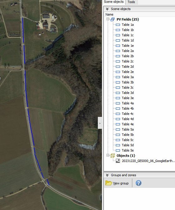
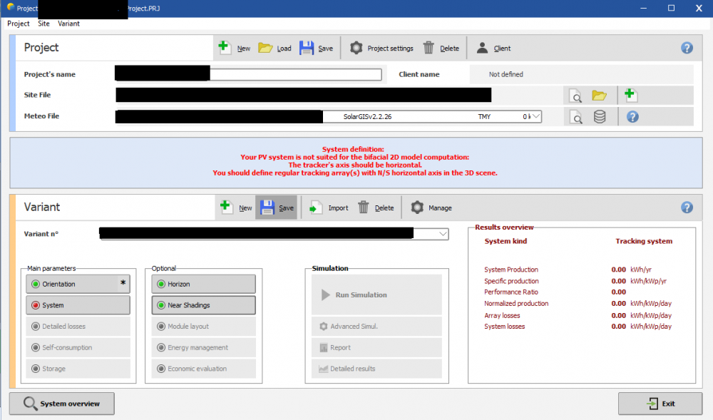
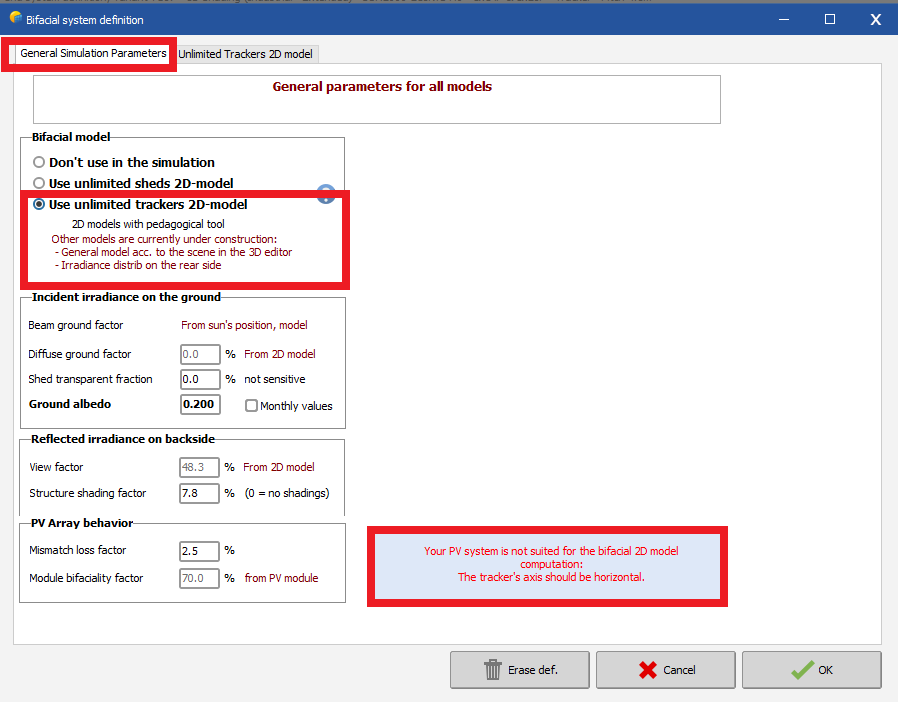
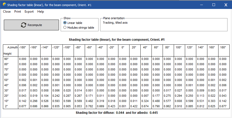
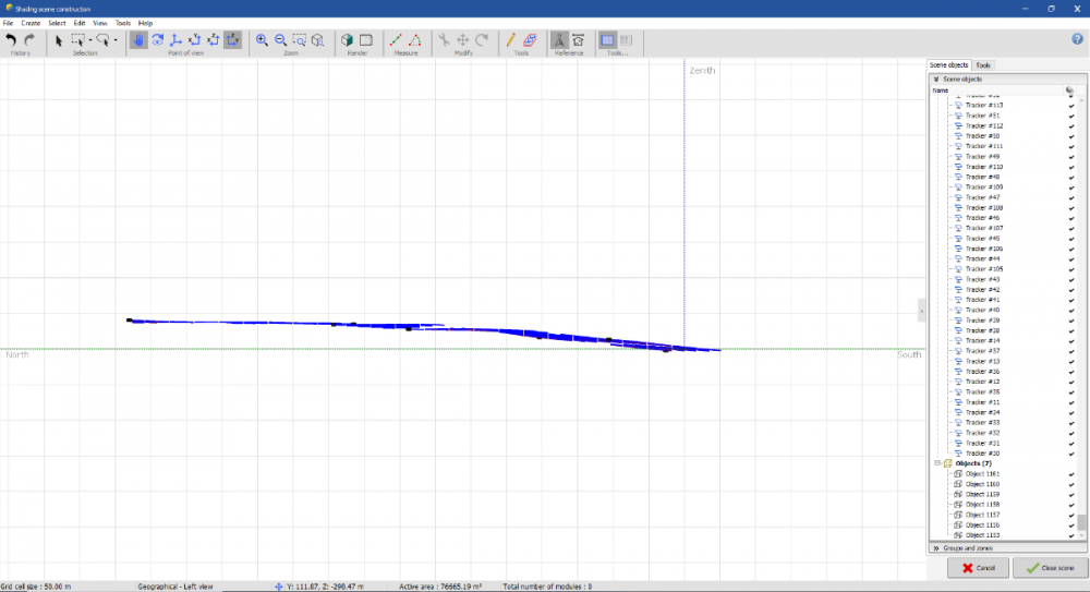
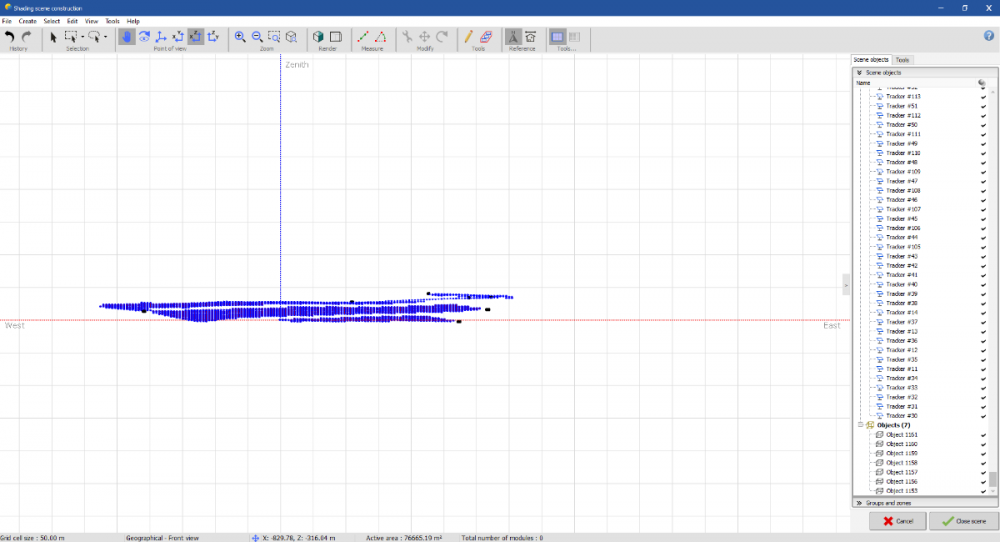
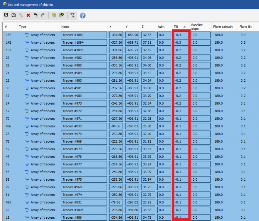
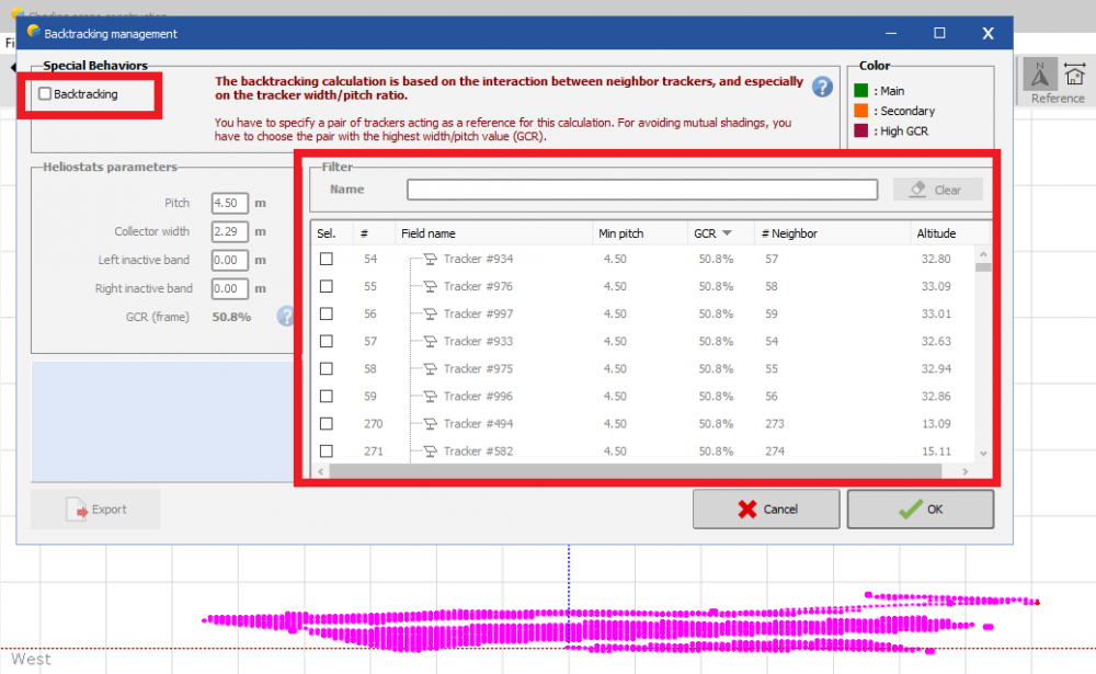
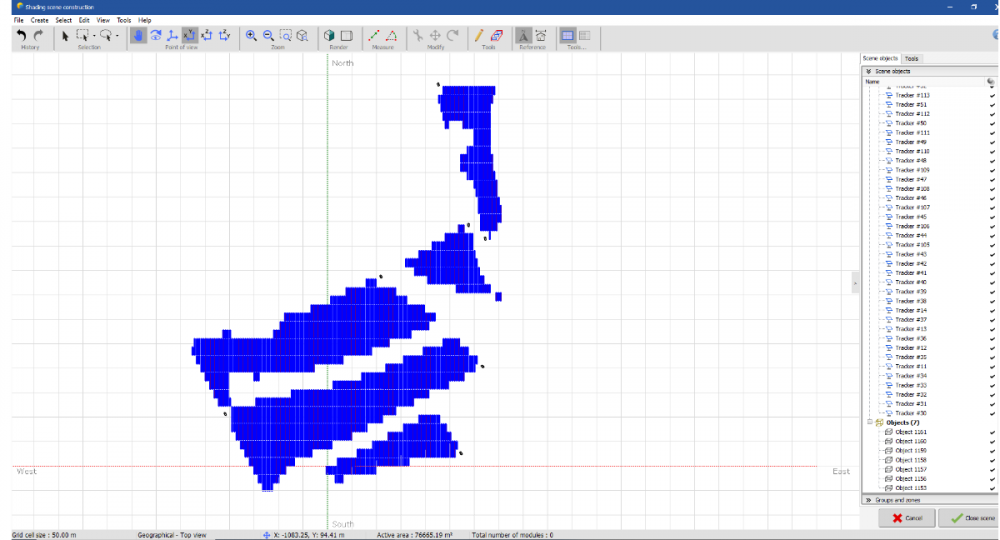
I cannot simulate tracker's 3D scenes built with AutoCAD and plugings like PVCase or VirtuoSolar. With fix structure I was able to solve it by changing the tolerance in the "shading scene construction > tools > orientation management". Most of the scenes I am building are placed in sites where irregular terrain characteristics having NS tilted trackers with tilt angles from -8Dgr to 8Dgr is very common. In my projects computing 3Dscenes under this scenarios is a must specially because I need to use bifacial modules. PVSyst 7.2.12 Screen shoots How can I process this type of 3D scenes ? What I am doing wrong ? Thanks and regards M

