
André Mermoud
-
Posts
2075 -
Joined
-
Last visited
Everything posted by André Mermoud
-
With such an inverter, this is not advised (or not possible) due to the current limitation. However with other inverters (those with the secondary input dedicated to one only string, and when it is allowed by the manufacturer), you can indeed use only the main MPPT input. In this case you should inform PVsyst by using the "Adjust" button.
-
This is not possible in PVsyst. You should do different simulations with parts of your system.
-
I have given the answer to this question in my last post: However, since the redaction of this answer, the limits have been migrated to the Project's parameters (button "Albedo and Settings", page "Other limitations", parameter "Max. orientation difference for defining average (spread) orientation".
-
You have chosen an inverter with a special feature named "Unbalanced Inputs". This means that you have two different MPPT inputs (in this case, with Imax = 49.5A and 37.5 A respectivaly), named "Main" and "Secondary" inputs. With such special inverters, PVsyst requires that you define two different sub-arrays, one for each kind of input. In your case you will define the first sub-array for the main MPPT input, 3 strings and the corresponding orientation. And a second sub-array for the secondary MPPT input, 2 strings and the corresponding orientation. NB: You can add sub-arrays either by specifying the number (top left) or by right-clicking on the sub-arrays page titles. NB: The fractional and strange PNom values are due to the fact that the PNom of each input is shared as function of the Current's shares: 49.5A and 37.5 A lead to PNom = 13.7 kW and 10.3 kW.
-

Mismatch Loss Parameter; Irradiance and Temperature
André Mermoud replied to Dan Nicksy's topic in Simulations
PVsyst uses the one-diode model with slight modifications (especially an exponential behavior of the Rshunt as function of the irradiance). See the Help "Physical models used > PV module, model description". -
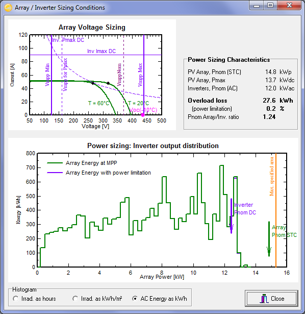
Usually the PV array very rarely reachs its nominal power during operation. Except under special partial cloudy conditions (transitory conditions), or at high altitudes, the irradiance perpendicular to the PV module doesn't exceed about 1000 W/m2. But in these conditions the PV array temperature is at its higher values. A PV cell temperature of 55°C, with a temperature coefficient muPmpp of -0.42%/°C, will induce a loss of 12.6° with respect to STC (1000 W/m2 and 25°C). Now the inverter sizing is not really dependent on this: you can accept some hours of overload without loosing much energy. PVsyst offers an explicit tool for the sizing of the inverter. You can see that a PnomRatio (= PnomPV / PNomInverter) of 1.25 to 1.3 is quite acceptable in most cases. Inverter sizing conditions

-
With "normal" projects, PVsyst responds immediately as any other software. A long response time may arise during some operations, for example when you have a very big shading system. This is usually due to a recalculation of the interpenetrating objects at each verification of the calculation version (shading scene). You can desable this option in "Tools > Ignore interpenetrations of shading fields" in the menu of the 3D editor. Another example: Meteonorm 7.1 takes some seconds for generating synthetic data.
-
Effective Energy at output of array doesn't match sum of losses
André Mermoud replied to nico7904's topic in Simulations
The difference represents 1.3% ... There may be some rounding uncertainty in the percentages, and the simulation procedure for stand-alone systems was not quite optimal in this old version 5.74 (there is some retro-action between the direct-coupled PVarray and the real battery voltage). With the next version 6.40 (to be released beginning of January 2016), the simulation of stand-alone systems has been deeply revised, and this balance is now quite correct (within 0.1 to 0.2%). -
assign modules to strings in module layout
André Mermoud replied to emreorhan's topic in Shadings and tracking
I don't know. Which version of PVsyst are you using? Did you specify "Mixed Orientation" for some sub-array? This could be an explanation for an old version. -
I don't know. Probably the PV array is not defined correctly (perhaps a Polygonal field, with points counted anti-clockwise, which means a down orientation ?). Please send your full project, using "File > Export project"in the main menu, to support@pvsyst.com).
-
Mismatch Loss Parameter; Irradiance and Temperature
André Mermoud replied to Dan Nicksy's topic in Simulations
In PVsyst, the mismatch parameter is a constant parameter that you can set at any desired value. Now in the explanations I have not mentioned this mismatch in irradiance on a big array. You can include it if you want. However please observe: - The mismatch in important when acting on the current, i.e. in a given string. But between strings in parallel, the mismatch loss is negligible. Therefore this contribution should only concern short-distance irradiance discrepancies. - The cloud's effects are transcient phenomena. Their duration may be considered as negligible when calculating averages over hourly values. - Such variability may be accounted in the meteo data uncertainties, especially in case of unstable conditions. -
Horizon Shading hourly - monthly difference?
André Mermoud replied to Rapha123's topic in Shadings and tracking
I don't know. Normally the values of a given variable should match between the monthly table and the hourly values on the ASCII file, as this is the same variable in the program. However you are right. I just tried and also observed a slight discrepancy (0.8%, i.e. 0.3 kWh/m2/year on the horizon loss in the monthly tables). This is probably due to accounting the monthly values when the Incident irradiance is below the threshold of 10 W/m2, what is not done in the hourly values. I will check. -
How can I know how many panels there are per inverter in PVsyst?
André Mermoud replied to Iggleton's topic in PV Components
Yes, within a sub-array, PVsyst will share the strings (not the number of modules) equally between the specified number of MPPT inputs. Now if you have, for example 9 strings to be shared between 2 MPPT inputs, one will have 5 strings and the other one 4. -
ASCII Import - Irradiance >1000 read as error
André Mermoud replied to samvance's topic in Problems / Bugs
Please check that there is no "Tousend character" in your numbers (like for example 1'000). -
The shading factor calculation will indeed be drastically improved in the next update V 6.40, to be released beginning of January 2015. However this problem is due to another problem (the verification of the shading scene), and desabling "Ignode Interpenetration of PV fields" should normally avoid it. If there is no improvement with the next version 6.40, please send us the full project to support@pvsyst.com, using "Files > Export project".
-
Shading: Linear and Acc. to Module Strings Yield Same Result
André Mermoud replied to Dan Nicksy's topic in Problems / Bugs
The calculation of the shading factor "According to module strings" is indeed not quite reliable in some special cases like this one. Please remember that this calculation should be considered as an approximate tool. The program analyses the shading state of each summit of the rectangle-string, and one intermediate point on the segment. Therefore a little shade on a part of the rectangle-string might be not recognized. For such a special condition, you should use the "Module Layout" option. Here the shading state of the corner of each sub-module is analysed. Now for the object not taken into account due to its base altitude, perhaps this is a result of the optimizing algorithm. In the 3D editor menu "Tools" please try to desable "Optimized shading calculation". -
How to compare the measured exported energy with the simulation?
André Mermoud replied to Sebastian.stan's topic in How-to
This is indeed the right way: in the part "Tools > Measured Data Analysis" you have to define the parameters corresponding to your system, and run the simulation. Now in the results dialog, you can open "Predefined graphs", and here you have several ways of comparing your data to the simulation. Sorry, this is a part of the program that has been neglected since a very long time. Even the DEMO project (N13 Motorway) doesn't work anymore. We will modernize it in a future version of PVsyst, and make this use more explicit and user-friendly. -
In PVsyst and for Northern hemisphere, North corresponsd to Azimuth = 180°. Please see our FAQ How is defined the plane Orientation ?.
-
Yes the sequence is correct. But at the point 3, the POA modeled should be equal to the input measured POA (within some few permille). If you observe discrepancies (in the morning or evening), this means that you have not imported your data correctly, or the data themselves are not correct. Please check your file in "Databases > Meteo Tables and Graphs > Check Meteo data", and here press F1 for explanations in the help (especially about the Timeshift).
-
Not directly in the report. The report has a fixed format. But the button "Monthly tables" allows to show (and print) tables of monthly values for any chosen variable among the simulation variables, including the PR.
-
You can now create a one-year Clear day meteo data (MET file) in "Import Meteo data", datasource "Clear sky model".
-
PVsyst simulation using spectral irradiance datasets
André Mermoud replied to ckoessler's topic in Simulations
In the present time, PVsyst performs an irradiance correction for amorphous modules only. Spoectral effect is usually admitted as rather low in yearly simulations for crystalline modules. We will probably develop a possibility of taking a spectral correction into account in a next version, but not before several months. This is not in our first priorities. By the way such a tool will deal with spectral corrections models (as a function, for example, of the water contents of the amosphere). Now for the use of a reference cell, please see our FAQ For Meteo measurements, should we use a pyranometer or a reference cell ? -
Sorry, in the present time PVsyst defines user's needs in terms of global load energy, and doesn't involve inverters. This will be developed in a next version.
-
No sorry. PVsyst works with one full-year entities or datasets, and never covers several years at a time. However, after importing your meteo data one by one, you can use the batch mode for performing the yearly simulations in a same run.
-
In principle, in recent versions, when you have meteo data created by original POA data, PVsyst doesn't allow to use the Perez model for the next transpositions. Using the Perez model should obviously give different results (not matching your input POA values).