Chen
-
Posts
50 -
Joined
-
Last visited
Everything posted by Chen
-
thanks!
-

-
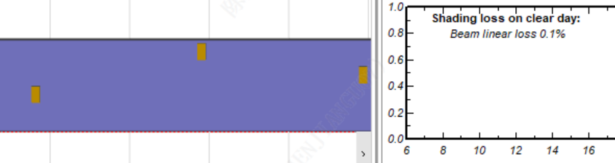
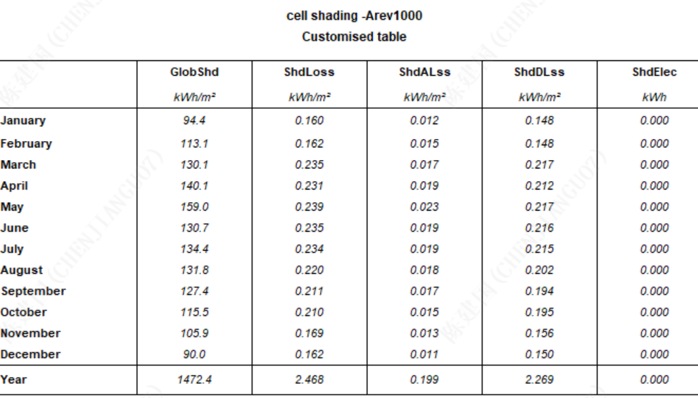
Dear sir: Recently, when simulating cell-level shading of PVsyst 8.0.19, I placed the shading object about 1-2 cm away from the PV module surface to simulate the bird droppings shading. Simulation results showed that the percentage of electrical shading loss was almost zero, Yet the 3D modeling confirmed that shadows were cast on the module surface. What might be the cause of this? Thanks!
-

Arev factor of BC modules in string level simulation
Chen replied to Chen's topic in Problems / Bugs
What are the testing conditions for Arev? thanks! -
Arev factor of BC modules in string level simulation
Chen replied to Chen's topic in Problems / Bugs
thanks! -
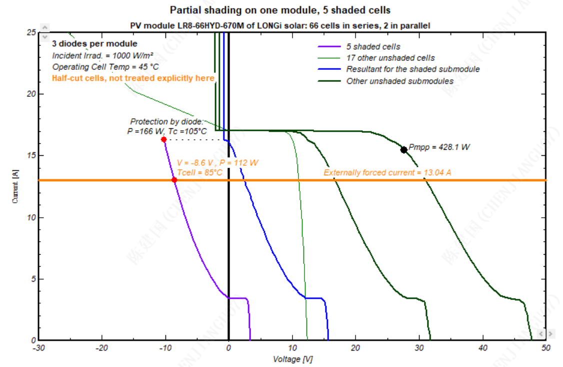
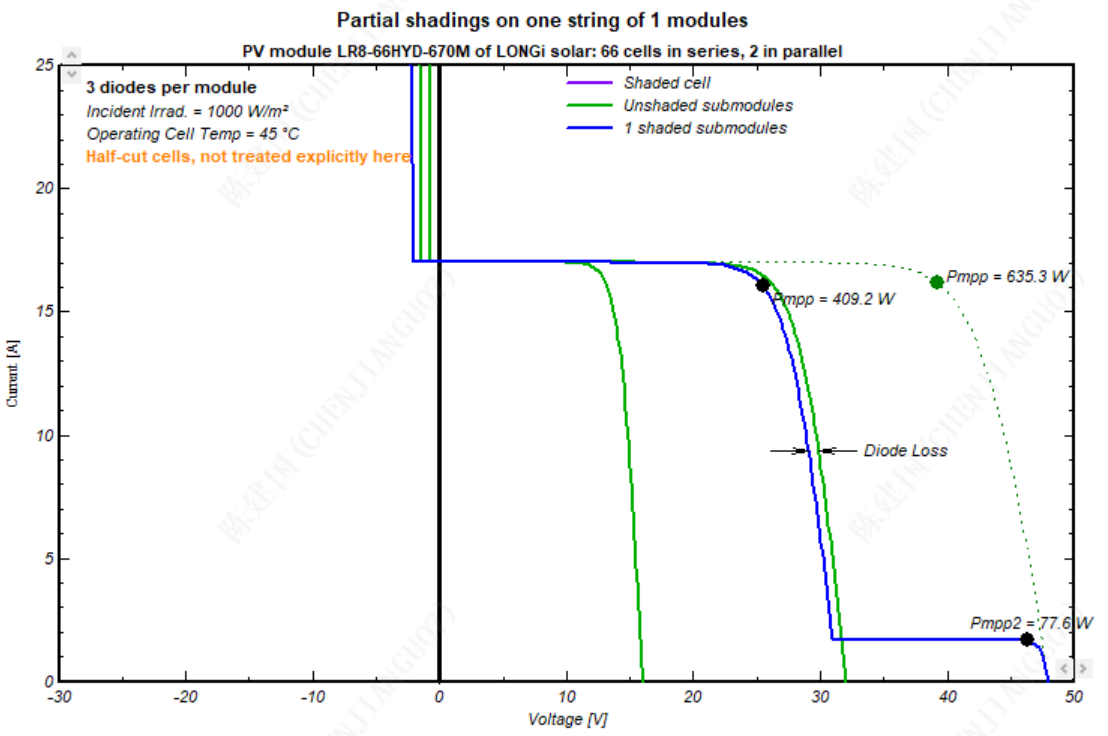
Dear Prof.André Mermoud: Recently, I have utilized PVsyst 8.0.19 for simulating the IV curves of BC modules under module-level and string-level shading scenarios. Given some inconsistencies identified in the string-level results, I wish to arrange a discussion with you on this matter. I increased the Arev factor of BC module to over 1000, and first simulated cell shading at the module level with 1 cell shaded. The results showed a 35% power reduction. When I used the string simulation tool to replicate the same number of shaded cells—i.e., a string configuration with one module per string and 1 cell shaded—the results displayed a significant discrepancy. Does it a bug? Does the Arev factor of BC modules fail to take effect at the string level? thanks! Best regards!
-
Report shows spectral correction applied even when it isn't
Chen replied to LauraH's topic in Problems / Bugs
OK, thanks -
Report shows spectral correction applied even when it isn't
Chen replied to LauraH's topic in Problems / Bugs
what does the C0 C1 C2..C5 mean? thanks! -
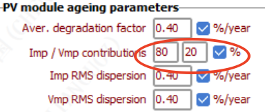
Dear PVsyst team: For the Imp/Vmp contributions 80/20%, is there any relevant literature to support the value of this parameter? Thank you!
-
OK,thanks
-
Ok,I wonder if our software can be considered this.
-
Dear sir: For the bi-facial module system , when calculating the cable loss of strings, should the current on the rear side of the modules be considered in our software? thanks!
-
OK, u are welcome
-
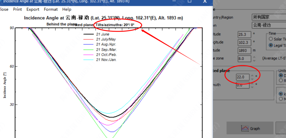
Dear sir: I found that the inclination angles of the two are not the same. Is it a bug?THANKS
-
OK,thanks very much!
-
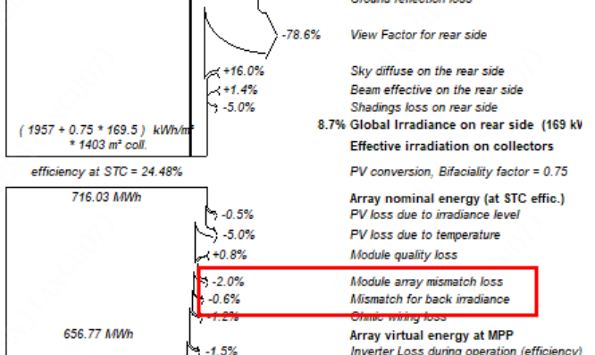
Dear sir: Can you take a look at this problem? Why is the backside mismatch loss calculated separately from the front side, rather than being added to the front side like irradiation. thanks!
-
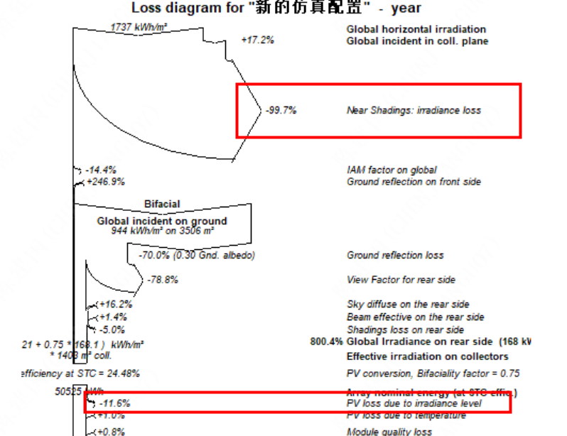
When I completely shade the front side of the module and allowed the back side to receive light, I found that the loss due to weak light was relatively high.
-
OK,Thank you for your detailed answer.
-
ok,I agree with your viewpoint, but do you think this calculation is reasonable? if the fornt side of module receive irradiance of 1000 W/m², and the rear side of module receive irradiance of 200 W/m², front side:(f × 22- f × 22) / (f × 22) = 0% (relative) rear side:(f × 21.34 - f × 22) / (f × 22) = -3% (relative)
-
I understand. What I mean is, if the irradiation intensity on the back of the module is relatively low while that on the front is relatively high, so does it imply that the low-light performance of the rear side is worse?
-
Because the irradiance of the front side or the rear side of PV module will be different, in this case, there will be a difference in conversion efficiency between the front and back sides,with respect to 1000 W/m².
-
thanks
-
Dear sir: Has the software taken into account the low-light performance on the rearside of bifacial module? thanks
-
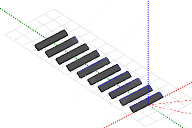
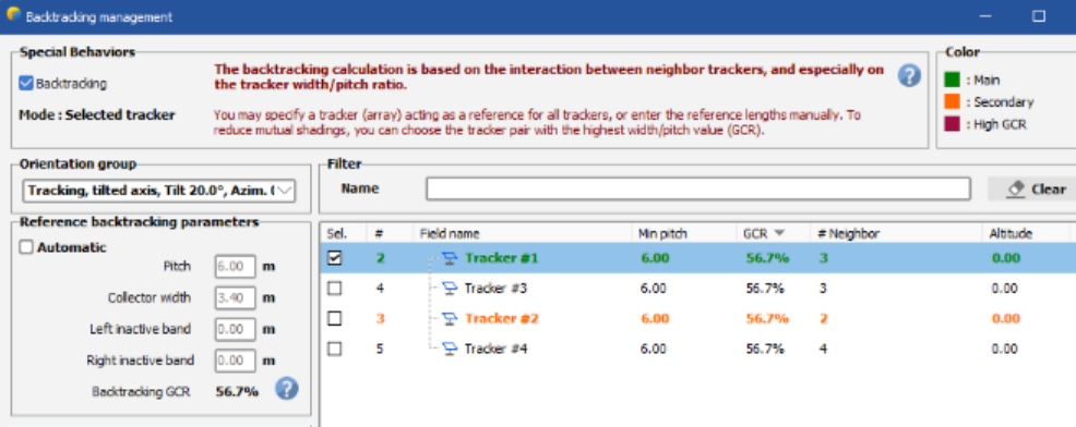
Dear pvsyst team: If I have an irregular trackers system, with some different pitches and GCR, what is the difference between the reference trackers and automatic mode ( deselecting the reference pair of trackers)?what is the automatic mode? thanks!
-
OK,thanks.