Michalis Angeli
-
Posts
92 -
Joined
-
Last visited
Everything posted by Michalis Angeli
-
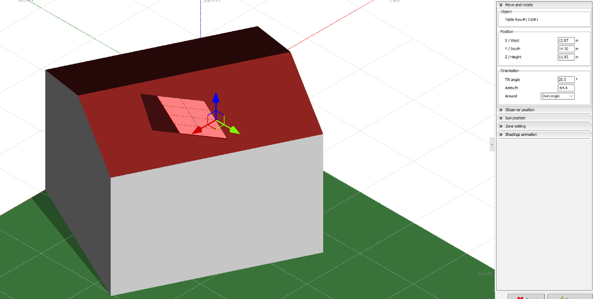
Hello I would like to ask, which azimuth should to define in pv panels in my project in order to follow exactly the same azimuth with tiled roof. The tilt angle I defined it without any trouble. But I defined the house azimuth angle equal to -64.6. When I define the same azimuth angle to pv panels I have the below reuslt. How can I solve it? Which azimuth angle should define in pv panels in order to follow the tiled roof?

-
Okay thank you very much is more easy than I thought! Thank you.
-
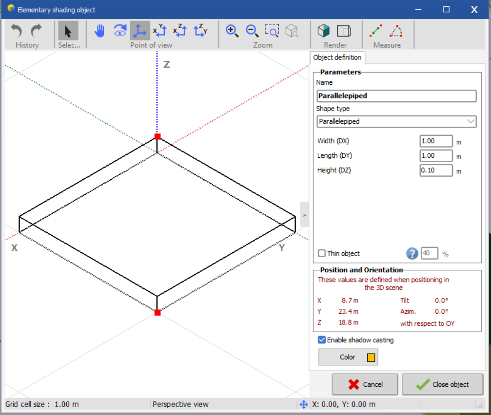
Very well, thank for your immidately response. Furthermore i would like somethnig else. Is there the opportunity to define angle or azimuth in an elementary shape like in parallilepided? I want to position it in a roof with specific angle and azimuth.
-
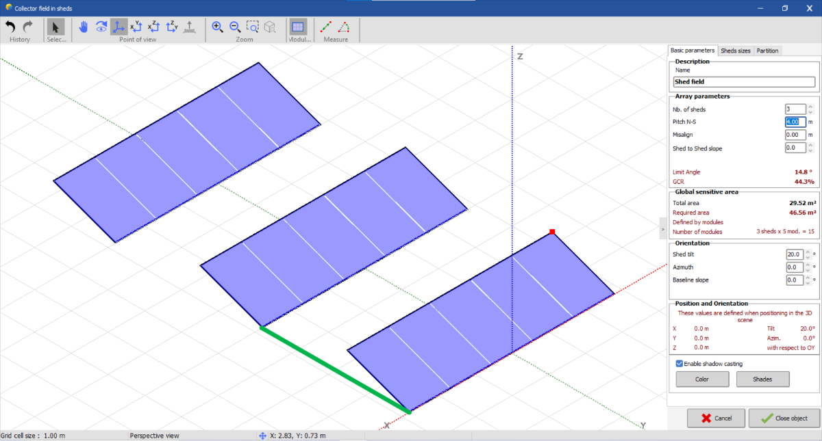
Hello, i would like to ask about shading scene. The distance (to this example 4 m) that named pitch N - S between 2 tables of panels is that I noted with green line, in below picture?
-
Hello, I would like to ask if there is option in report simulation, the 3d scene to presinted in realistic view;; Like the photo..
-
Hello dear Linda, First of all thanks for your response. I would like to ask if I can define a similar system with option peak shaving. But in my case I don't want to inject energy either from solar panels or batteries to grid system. Actually, i want to design a Zero feed - in system. Thank you!
-
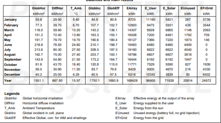
Hello, I am trying to simulate a project which is not allowed to injects energy to the grid. After I have defined the montly consumptions and the storage system, I ran simulation and I took this report Can you explain me what Battery Out, inverter loss means? and why is too big? Furthermore i didn't unterstand what are the three last columns in this table: I need explanaition and on this point. Thank you very much!
-
Partial shadings of some sub-modules: when one or several cells are shaded, the whole sub-module becomes reverse-biased, the by-pass diode is activated above the current corresponding to the residual power of the diffuse part. This results in a quite different situation as the previous one: the true Pmpp maximum is decreased in voltage (voltage of each sub-module, plus the diode reverse voltage), but the current remains the same Impp. I would like to ask if that sentence "the true Pmpp maximum is decreased in voltage (voltage of each sub-module, plus the diode reverse voltage), but the current remains the same Impp". is the result (a benefit) by using optimizers ?? Thank you!
-
Very well, thank you!
-
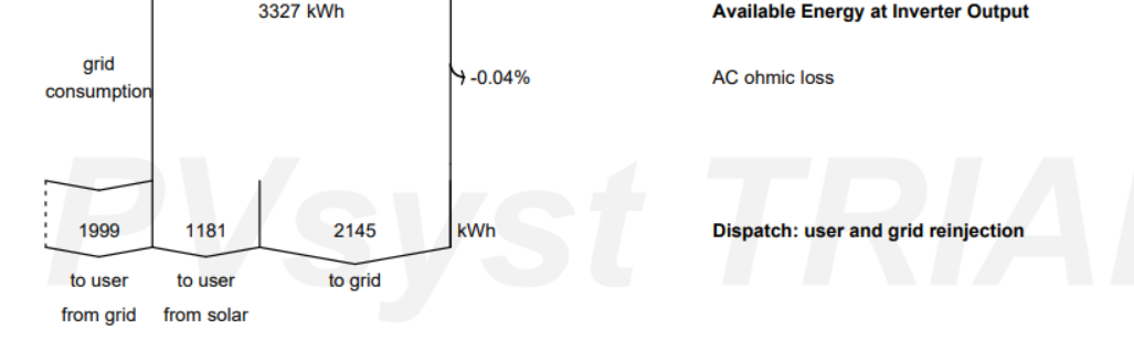
Hello, I would to clarify, what does is the energy to user from grid, and the energy to user from solar? Also, the sum of energy to grid and energy to user from solar is the Available energy at inverter output (ta ac ohmic loss are neglidenced) Thank you!
-
Very well, that is unterstood I ask all of these because this period i am investigating the effect of optimizers in this point "combine these two orientations into a single string, the overall production would always be limited by the orientation with the lower power output" . But as I unterstand that not possible and accetable from pvsyst due "the combined string's production would never reach its full potential due to the constraint imposed by the least productive orientation" And the mixed orientation means that i have the same inverter to mixed two orientation but not compine the orientations in one string, right?
-
Okay thank you very much!
-
Okay, thank you very much!
-
Hello again Linda, i want to clarify something. That you say here " the average length of one string (including 23 modules) is 33m" , you mean the length of dc cable right? Because i defined it as 33 m, considering that length. In our case we don't use main box and in this way we consider the length of one stirng the distance between panel and ivverter. Thank you.
-
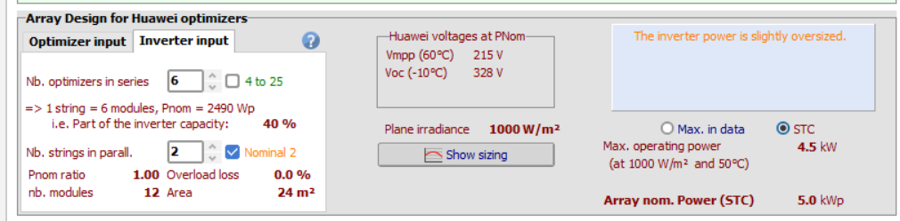
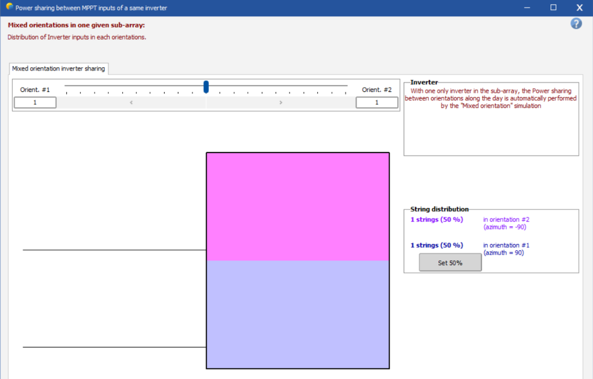
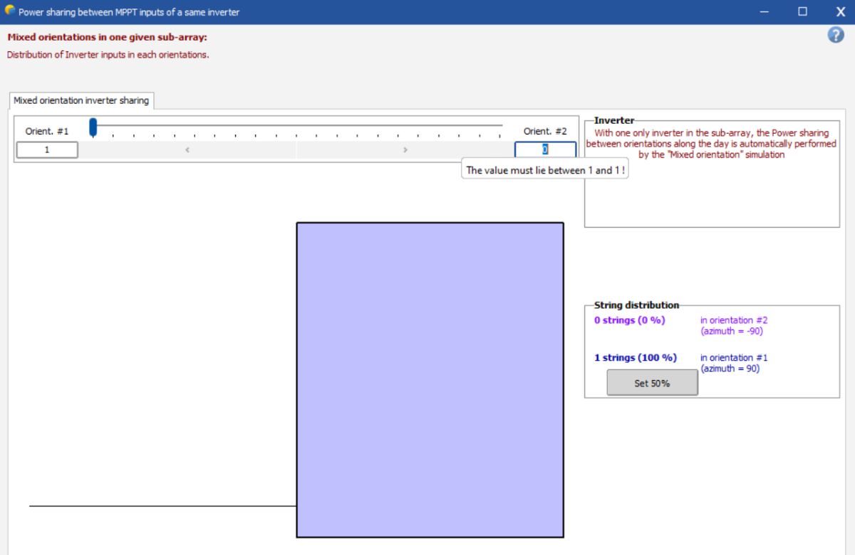
Dear Linda, In this case. I have 2 orientations. I use the Orient. Mixed #1 & #2. I have one inverter with 2 MPPT inputs. With option Nb. strings in parall.: 2. That it means, I have two strings parallel in one mppt input? I ask this because, in orient distrib., I have that. And I am confused, because of the fact we can't to define pv modules in series with several orientations, in one string. How that is possible? And how the option Orient mixed #1 & #2 work? Thank you!
-
Okay thank you!
-
Okay thank you very much. According with the bug that you referer. Is not a problem at present time, right? I can ran my simulation in the way you suggested me ? Thank you.
-
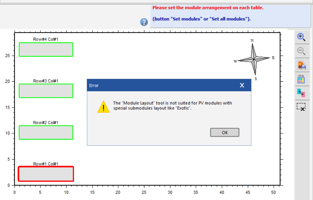
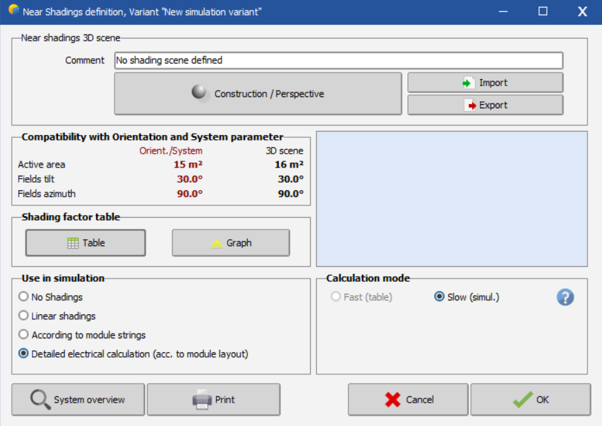
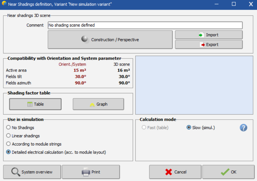
Hello I am trying to use the shading in simulation. I select the option detailed electrical calculation (acc. to module layout). When I go in module layout, despite my strings are showned in the layout, appears that error. How can I solve that? Thank you.
-
Good morning, I have that error. How can I solve that?
-
When I try to do that I descripes above, in this dialog. The system appear this error: How can I solve this? Thank you.
-
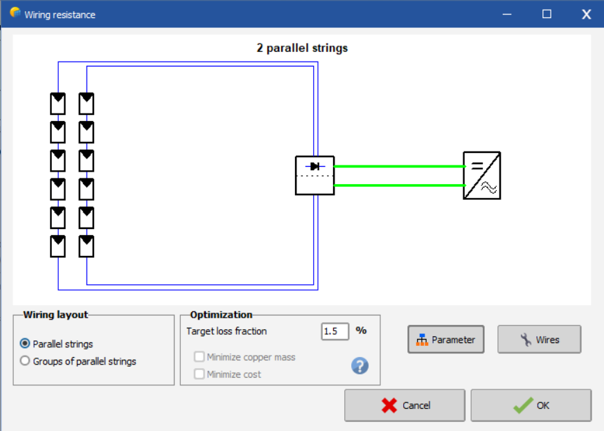
Hello, thank you for the answer. I tried your suggestion but i don't want to have 2 parallel strings, and each string to has 6 modules. I want to have 1 string with 12 modules (the first six panels has ohter orientation than the others six panels), however I want to have one string with 12 panels together. How can I define this?
-
Hello, I would like to ask, if I can define optimizers only in several pv modules in one string. For example I have a string with 10 panels, but only the three of them are shaded, so i want to calculate the losses by define opitmizers only in theese panels. How can i do that?
-
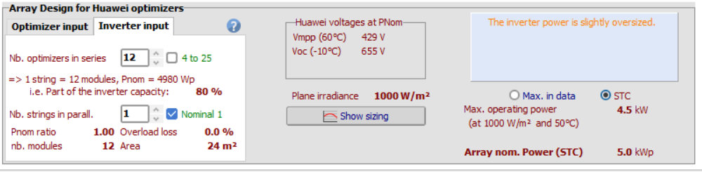
Hi, I would like to ask how can I define my system and use only the one Mppt Inputs from one inverter which has 2;; More specific, i use the SUN2000-5ktl-L1 and i want according my project to use only the one mppt input. Take into acccoun the fact, that the roof has two orientations. But i can't use mulitple mppt inputs because the total installation power is 4 kw that means I use only 9 pv panels. I can't to split them in two strings because the inverter will not has the requires voltage input to start up. So i want to construct only one stirng with all panels. How can I define it ?
-
Thank for your answer. Furthermore i would like to ask something more. I am trying to simulate an installation (5 kW) with 2 orientations. I want to connect all pv panels in one string in one mppt input. I want to check the efficiency of my project using optimizers, in two tiled roof installation. If I uncehck use multiple mppts inputs the system warning about the inverter is strongly undersized. Can you help me?
-
Hello i would like to ask in this case i use optimizers. Which type of shading should I define in Use in Simulation; According to module strings or Detailed electrical calculation? Thank you.