


julmou
-
Posts
106 -
Joined
-
Last visited
Posts posted by julmou
-
-
@André Mermoudany thought on my previous post addressed to you? :)
-
Good morning,
I find the SMA "JP" models quite useful for low voltage systems (short strings): Sunny Boy 3500TL-JP-22 and Sunny Boy 4500TL-JP-22.
I wanted to update the database with the newer version "Sunny Boy 5.5-JP", see link: https://www.sma.de/en/products/solarinverters/sunny-boy-55-jp.html
However I have mainly two interrogations:
- In the datasheet, the efficiency is specified with "JIS Efficiency". I know what CEC and EURO efficiencies are, but it seems that a Japanese standard is used here. The problem is that I don't know how to translate it into the table in the "Efficiency curve" section of the inverter definitions (only the EURO and CEC efficiencies are calculated). Would it be worth implementing this JIS efficiency into PVsyst?
- Also, I don't know what to make of the output voltage at 202V. How are you supposed to connect it to a grid or to appliances?
Thanks in advance for the help.
Julien
-
Good morning,
I was reading this post in the FAQ from 2012 by Andre Mermoud:
https://forum.pvsyst.com/topic/83-can-i-define-a-system-with-2-orientations-on-a-same-inverter/
QuoteHowever when putting modules of a same string in 2 different orientations leads to a the mismatch in current (due to different irradiances), which may be very important. This would be a very bad system and PVsyst doesn't allow it. This configuration would only be acceptable when using optimizers performing MPPT at the module level, but this is not yet implemented in PVsyst.
However, I do know of some installations in Perth in Australia, with different orientations on the same string(for example, when the roof facades are pretty small and there are only 3 modules on one side -> this is not enough in terms of voltage to make it a separate string, hence, it's connected with the other roof side which has 8 modules for example, making it a "polystring" of 11 modules with mixed orientation).
I acknowledge that this might be a bad design, however, sometimes the house constraints don't allow another option, and it would still be interesting to know the production and the losses in that situation, and be able to compare a variant with just the 8 modules on a single orientation vs. the 11 modules with mixed orientation, and see what's the benefit.
Finally, we are asked more and more to design systems with SolarEdge optimizers and inverters, it would be interesting if we could simulate a single string with mixed orientation and optimizers. Any update on this?
-
Hello,
I was wondering how you can tell an inverter with unbalanced MPPT from one that doesn't, based on the datasheet.
I am creating new Inverter Definitions with some of the newest SMA Sunny Boy and Tripower, in the 3.0-4.0 kW range, that aren't in the PVsyst database.
And I just don't know if these newer versions of Sunny Boy, or these low-power versions of Tripower, have the unbalanced MPPT option (which would be useful in my case).
I tried to compare with datasheet of higher-powered Tripower but couldn't make out any info/data that would tell if it accepts unbalanced MPPT or not.
How can you tell? Thanks so much in advance.
-
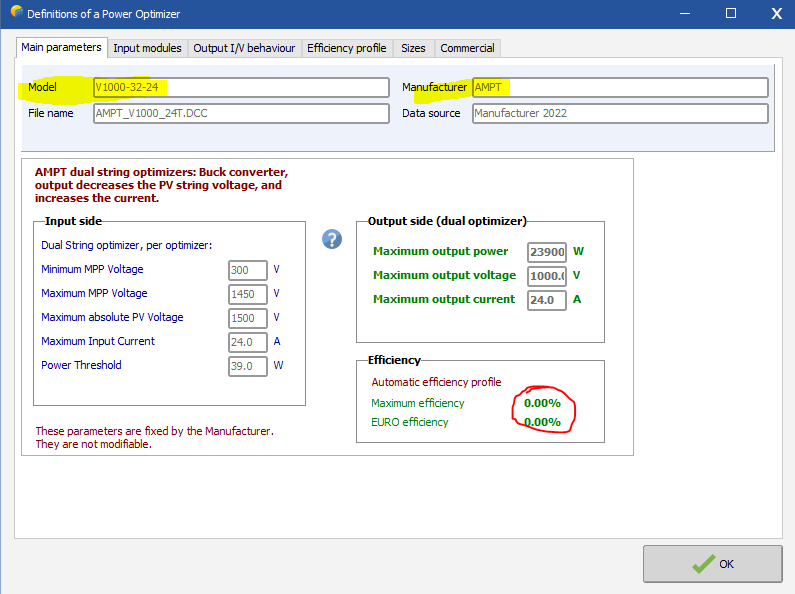
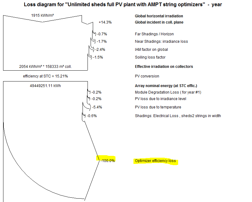
Hello,
I wanted to simulate some of our utility-scale solar farms with a repowering by adding String-Level Optimizers, from AMPT.
Now, the issue is that I can not get a proper simulation because I realised almost all AMPT Dual String Optimizers have an efficiency of 0.00% in their definitions, resulting in 100% loss due to Optimizer's efficiency during the simulation, thus 0 MWh production at the end.
Would it be possible for the team to remediate to this? :)
See screenshots below
Thank you so much

-
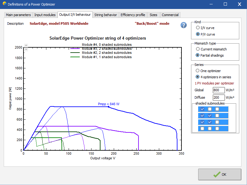
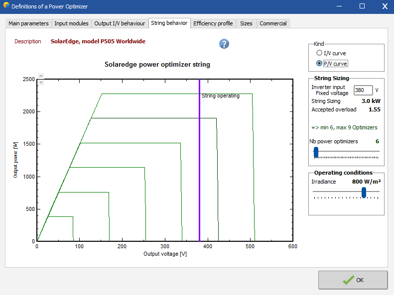
I also have a question regarding the fixed voltage of a SolarEdge inverter input.
I have a system with one string of 6x DualSun 500Wp modules and 1x SE3000H inverter. This is on a residential house that is quite prone to shading.
From what I observe with the "Output I/V behaviour" tool, in the definitions of a power optimizer, in case of heavy partial shading, the MPP power plateau shortens at the string level -> see screenshot of the P/V curve below (example with 4x optimizers in series)
We can see in this case that the voltage range, at the string level, to keep the Pmpp is between 60V and 190V (not until 340V anymore, as was the case without shading).
If we have 6x modules/optimizers in series (see 2nd screenshot below), with a fixed voltage at 380V, and no shading -> this is okay, the Impp of the string and the various Vout of each optimizer will adjust accordingly to deliver the Pmpp.
But if we have a heavy partial shading (as shown in the previous case with the 4 optimizers in series), we can see that the MPP power plateau could shorten and the Pmpp might only be achieved under a voltage lower than 380V. Hence having a fixed voltage in this case could incur losses.
Help me understand this... Is this correct? It would seem then that under certain circumstances, having an inverter input fixed voltage with optimizers might a disadvantage rather than a benefit?
-
I've recently been diving into the topic of Power Optimizers, which I thought was pretty simple, but their behaviour is actually more complex than I thought.
So, I just want to clarify something about what I've been reading in the Help Documentation. See screenshot below -> two questions written in bold
-
Thanks for the answer.
I understand that, with unlimited sheds, or unlimited trackers, the GCR is the width/pitch, because the only gap is between each rows. But with heliostat systems (with a rotating table on a vertical axis or on dual axis), there are gaps in two directions (NS pitch, EW pitch), so I was wondering how we could compute the GCR for those systems.
I'm asking because I find the GCR to be a good indicator of the use of the land. For instance, we might have vertical axis trackers that are more effective than horizontal one, but if the space they occupy in order to avoid mutual shadings is too big, the question remains if it's really worth it -> which is where I find the GCR to be a good indicator for land occupation, but not sure how to estimate it when we have a pitch in two directions.
... after some thinking, I believe an appropriate answer for the GCR/land occupation indicator in this situation could be: (Coll. Width * Coll. Length) / (NS pitch * EW pitch)
-
This is not what I meant. I'm okay with the names. I just thought an array of tables would be converted into an array of trackers, and not into single trackers.
-
Anymore inputs on this topic?
Anyone from PVsyst?
-
I am using the latest version 7.2.14 on Windows 7 32bits
As soon as I click the "Slide rows" button, I can't do anything else, I can not click anywhere or ESC or cancel, the PVsyst program is just frozen.
See video here:
-
Good morning,
I was testing the different functionalities of the "Zone editing" tool, and it seems that every time I try to use the "Slide rows" button, the software freezes and I have then no other option but to forcingly close the program and reopen it. I tried in different configurations, it has always the same effect. Is it only on my machine or a bug encountered by every one?
See the two screenshots below to understand the button I'm talking about.
Thanks for the help.
-
When you have an array of vertical single axis trackers or an array of dual axis trackers, how do you calculate the GCR? See two examples below.
Example 1: 4x arrays of dual axis trackers, each with 15m pitch E-W and 0m pitch N-S
Example 2: 4x arrays of dual axis trackers, each with 15m pitch E-W and 10m pitch N-S
-
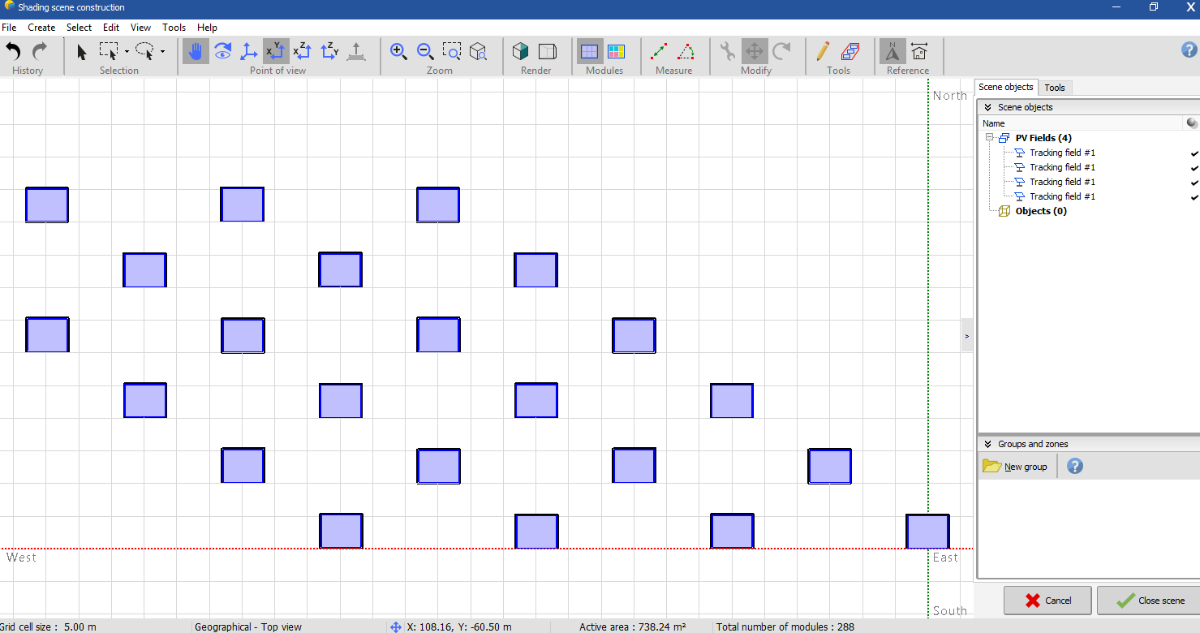
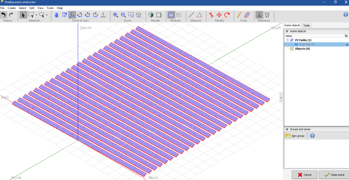
Hello,
Starting with a PV shed field with 24 rows (as an array of tables) -> see first screenshot below, I am surprised that, when I convert the array into trackers (Create > Convert fixed tables to trackers), I get 24 objects each qualified as an "array of trackers" (when really each is a single table), instead of obtaining one single array of trackers of 24 rows -> see second screenshot
Am I doing something wrong in the manipulation?
-
Thank you for the answer.
Have you also considered listing the tracker manufacturers in the Database?
It gets really tricky to find what the offer on the market is, especially with tilted or vertical trackers or dual-axis.
Besides, it would be a wonderful comparison tool, being able to see that such and such system have stroke limits of 60°, while this one has 80°, and perhaps this one has backtracking and the other not, and perhaps the same manufacturer offers a range of options with tilted single-axis trackers, etc.
-
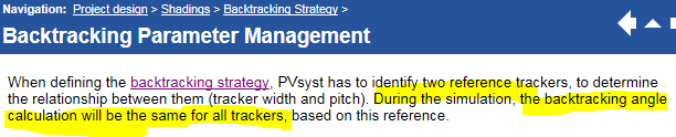
A thought occurred to me as I was reading this part of the documentation: Project Design > Shadings > Backtracking Strategy > Backtracking Parameter Management. See screenshot below.
QuoteDuring the simulation, the backtracking angle calculation will be the same for all trackers, based on this reference.
So basically, on the typical 50, or 100 or 200 MW solar plants here in Australia, there are thousands of trackers. And the way it's simulated, is that ALL trackers move exactly at the same time and do the same exact movement with the same angle. And I assume that the simulation is making it so that it is back-tracking only as much as it needs to, based on the sun's position and the incidence angle, so this is assuming that every single tracker on the field also has the utmost precision estimating or measuring the sun's position and deducing the right angle to adopt.
My point is, I think the way it's simulated is too perfect, and I doubt that:
- all trackers move exactly at the same time, hence there is some kind of mismatch loss, due to the trackers being slightly not all in phase with each other (in practice, they are indeed independent, and wouldn't all move exactly the same way like in the simulation),
- and I also doubt that they all have the correct perfect angle, there's maybe some margin to make absolutely sure that there isn't any mutual shading, and I also believe that whatever the way they estimate the proper angle to have at any time, there is some uncertainty in the process
For these two reasons, I was thinking that it would probably be adequate to incorporate in PVsyst a type of "tracking losses" section, with for instance, a mismatch loss, and an "imprecision" or "inaccuracy" or "miscalculation" loss. What do you think?
Besides, maybe it's unrelated, but all tracking solar farms I have re-created so far in PVsyst (with backtracking) perform much less in reality that in the simulation, with the difference being quite notably bigger than what I get with sheds solar farms.
-
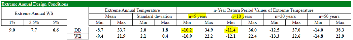
Thanks again for the link, this is a great resource. I'll save it in my bookmarks. From the two projects I studied in Australia, at Royalla Solar Farm (near Canberra), they opted for a Tmin of -6°C, which correlates with the min temperature at 5 years from your screenshot. With Bungala Solar Farm (Port Augusta), they opted for a Tmin of +5°C (which, I already mentioned, seems dangerously high to me), and the ASHRAE data gives extreme min temp at 5 years -1.5°C, and at 10 years -2.3°C (see screenshot below).
It does feel to me though, that most design decisions on this aspect are not really conservative (often matching the min temp at 5years rather than 10 or 20 years)... ?
Would we be right in thinking that, if a manufacturer gives a max. input voltage Vdc-max at 1500 V in the datasheet for an inverter, that there is some tolerance margin and that the equipment could handle, say 1520 V, once or twice or year?
The PVsyst Help (Project Design > Grid-connected system definition > Array voltage sizing) mentions:
Quote- Absolute Cell lower temperature for determining the Maximum possible voltage of the array. The default is set to -10°C for most European countries (best practice rule).
For this limit, the cell temperature is considered as the ambient temperature (worst case when the sun suddenly appears on the field).
You should define the lowest temperature ever observed during the day for this site.
-10°C being the default value, if we observe the Geneva data from ashrae-meteo.info/v2.0, here again it matches more the min value at 5 years rather than at 10 or 20 years, so not that conservative.
I find it interesting/strange that this is accepted as such a broad "go-to" value for most of Europe, where the lowest temperature observed during the day at Geneva or in Spain or in Hamburg, is obviously going to be very different (screenshot below for Hamburg, where -10°C really doesn't seem appropriate)... ?
It would be interesting to know the thoughts of a PVsyst moderator too on this topic of choosing the right "Lower temperature for Absolute Voltage limit" ☺️
Bungala SF, Port Augusta:
Geneva Cointrin, Switzerland:
Hamburg, Germany:
-
@André MermoudThank you, this is really helpful. I work mostly with Australia where the latitude goes from 12° S in Darwin, 27° in Brisbane, 34° in Sydney, to 38° S in Melbourne, or even down to 43° S in Hobart, Tasmania or in New Zealand. I am trying to get a method or a rule of thumb where I could quickly adapt a similar system from one latitude to the other by adjusting the pitch.
-
With sheds, basically what you're saying is "In low latitudes [...] you can diminish the pitch". The reciprocal of that would be to increase the pitch as we get higher in latitude, which I understand (sun lower on the horizon, mutual shadings accentuated, hence the need for more pitch). However, this seems to go against some of the advice I had gotten from the Help (Project Design > Plane Orientation > Optimizing sheds) where the last paragraph states:
And from the Forum FAQ (Shadings and tracking > In sheds arrangement, which power can I install on a given area ?), where you mention:QuoteWith shed installations, choosing a rather low tilt is often a very good solution [...], with the following advantages: - The installable power is much greater on a given ground area.
With sheds, opting for a low tilt results in being able to have our PV rows closer to each other, with a lower pitch. So, I guess, where I'm confused is that on one hand, we are advised to cover more ground and put as many panels as possible, which means lowering the pitch, and on the other hand, we are advised to increase the pitch to reduce the mutual shadings as we get higher in latitudes. Could you help me understand how to compromise between the two? With sheds, as we get higher in latitudes, is it always better to steadily increase the pitch, or do we reach a point at some latitude where it makes more sense (as the irradiance gets lower) to put more rows and panels instead and compensate the reduction of irradiance due to the low latitude with a lot of PV coverage (with low tilt), which means lowering the pitch?QuoteTherefore when the area is limited, you are always advised to put your collectors as horizontal as possible
- With horizontal single-axis tracker (HSAT) with N/S axis, we actually have quite a large amount of these systems in Australia (sunny place -> good for trackers), most notably in a one-module-in-width, portrait arrangement. I tried to compare and see a trend for the pitch according to latitude with these same systems (all with backtracking):
Clare SF -> lat. 19.8°, GHI 2020 kWh/m2, pitch 5.7m, GCR 34.4%
Hamilton SF -> lat 20.5°, GHI 2016 kWh/m2, pitch 6.9m, GCR 28.4%
Degrussa Gold & Copper Mine -> 25.6°, 2244 kWh/m2, 5.2m, 37.7%
Agnew Hybrid Power Station -> 28°S, 2159 kWh/m2, 5.3m, 37%
Moree SF -> 29.6°, 1994 kWh/m2, 6.2m, 31.6%
Bungala SF -> 32.4° 1970 kWh/m2 5.1m 38.4%
Yatpool SF -> 34.4° 1917 kWh/m2 5.4m 36.3%
Williamsdale SF -> 35.6° 1761 kWh/m2 7.5m 26.1%
There doesn't seem to be a real trend, neither according to latitude, nor to irradiation. I do use the Optimization Tool, but just like with sheds, basically the higher the pitch the better it is (not only less near shadings from the beam component, but also more irradiance from the diffuse and albedo, as we increase the pitch). And in reality, we can not increase the pitch indefinitely, so where do we set the bar? Again, for a given system (in this case HSAT N/S axis 1x module width portrait), shouldn't there be an easy rule, for setting the pitch parameter according to the latitude?
Sorry for the long post, and I really hope you can shed some light on this. Thank you,
Julien
-
With sheds, basically what you're saying is "In low latitudes [...] you can diminish the pitch". The reciprocal of that would be to increase the pitch as we get higher in latitude, which I understand (sun lower on the horizon, mutual shadings accentuated, hence the need for more pitch). However, this seems to go against some of the advice I had gotten from the Help (Project Design > Plane Orientation > Optimizing sheds) where the last paragraph states:
-
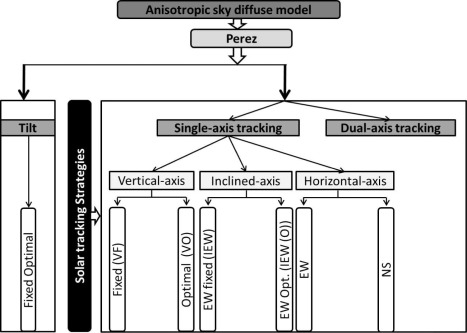
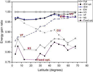
@Michele Oliosi This is an interesting study indeed, although I'm a bit dubious of some of the results. It seems the E-W axis is always outclassing the N-S axis all the way to latitude 55°, and with N-S only performing slightly better than fixed sheds... which is really strange! I mean, as you point out in the PVsyst documentation regarding E-W horizontal trackers: "This configuration is here for completeness, but is indeed not suited for PV systems." -> it only has a range of motion between the lowest and highest sun's height, which isn't a big angle, whereas the N-S axis has a broader range of motion, -60° to +60°, from east to west. Even when testing some cases in PVsyst, the N-S is always better than the E-W. Besides I don't know what the IEW system (Inclined East-West) would be, it's usually the N-S that can be tilted/inclined. Do you think the author might have mis-named between the two? and EW is actually a N-S axis tracking from east to west?
Regarding the vertical axis, the results are more believable, I tested some situations and the yield is actually really good and better than N-S trackers (even with irrad. optimization + backtracking). It is surprising though that we don't really see many PV plants with vertical axis trackers, the foundation + rotating system must cost quite a lot.
I attached further below the main graph from the study where I wrote the system's name on the curves themselves, it makes easier to read.
-
Thanks a lot, I wasn't aware of the Australian standard AS/NZS 5033, that's really helpful! I couldn't get my hands on the 2021 version, but I got the 2005 version and the amendments of the 2014 version in a separate document.
Well, for the case I'm studying, the inverter specs (Sunny Central 2500-EV) are "Maximum MPP Voltage: 1425 V" and "Absolute max. PV Voltage: 1500 PV", so I really think getting a good estimate of the max. voltage of your array is crucial for safety aspect and for not wearing off the inverters too soon after already a couple of years.
I am using two types of modules in this study: JINKO SOLAR 325 Wp PV MODULE (JKM325PP-72-J4V) and JINKO SOLAR 330 Wp PV MODULE (JKM330PP-72-J4V), with respectively Voc = 46.7 and 46.9 V, datasheet is attached.
The first version of the standard was pretty conservative (1.2 * Voc) and I would get an array max. voltage of 1681 and 1688 V, too high for our inverter.
Since the 2014 revision, if I use the method 1, I get 1514 and 1520 V. And if use method 2, I get 1569 and 1576 V. With PVsyst, I get an array max. voltage of 1521 and 1528 V. Now, with these 3 methods though, I used -1°C as the Tmin ("Lower temperature for Absolute Voltage limit", "lowest expected cell temperature in °C"). In my case, I inspected the ambient temp. values in the MET file (hourly values) and found the lowest one to be -1°C, at 6am, so just as the sun is about to rise.
Obviously, the engineers designing the plant opted for a higher Tmin value (which feels dangerously close to me, but let's move on). It really seems to me, the key here is how do you choose your Tmin?
- do you rely on site measurements? (at least a year? more than a year?), and if you don't have site data, do you take the nearest weather station?
- can you base your Tmin on the hourly values of the .MET synthetic file? I mean, even if it's synthetic, it is still based on 10+ years of recorded data, so you can expect the generated hourly values to be reliable, can't you?
- do you really have to take the lowest recorded temperature from hourly values (synthetic or measured), or would it be more reasonable to take like an average of the 10 or 5 lowest values, or the lowest monthly value?
-> I am genuinely curious how to decide the Tmin for a site. Thanks in advance for your help.
Julien
-
Good morning,
I have re-created some existing PV plants around Australia (near Canberra or near Port Augusta) and each time the Voc at -10°C is way bigger than the inverter absolute max input voltage. I usually have to adjust the "Lower temperature for Absolute Voltage limit" in the Project Settings, so that it would accept the sizing of the system as it is in reality (Voc temp. adjusted at -6°C for Canberra, and at +5°C for Port Augusta!).
Being mostly involved in projects in Africa or Australia or on tropical islands, these are warm places where, I assume, the -10°C best practice wouldn't apply.
My question is: is there a rule of thumb to know what's the Lower temperature for Absolute Voltage limit acceptable for a particular place? (e.g. take the average temperature of the coldest month and apply -10°C, or related to the latitude, or to the yearly avg. temp. or something like this)
Thanks,
Julien
Example with Voc at -1°C:
-
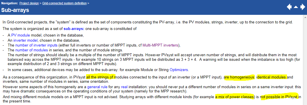
Good morning,
I was reading this section of the Help: Project Design > Grid-connected system definition > Sub-arrays and the part about which all the strings of modules connected to an inverter are homogeneous (identical modules) -> see screenshot below
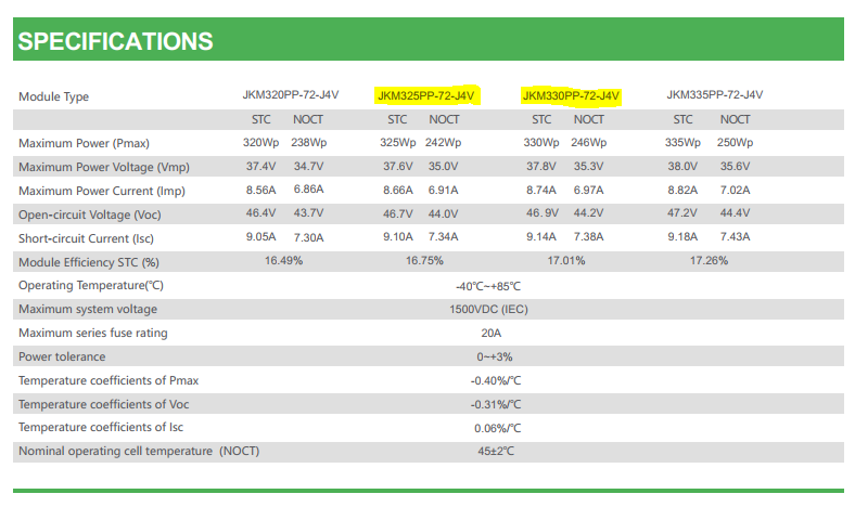
I was trying to recreate a former project of ours: Bungala Solar Farm in South Australia, actually one of the best performing PV plants in the country. And it involves a mix a two types of modules:
JINKO SOLAR 325 Wp PV MODULE (JKM325PP-72-J4V)
JINKO SOLAR 330 Wp PV MODULE (JKM330PP-72-J4V)
See datasheet below
Each inverter (Sunny Central 2500-EV) hosts 259 strings of 30 modules, of which 78 strings with 325 Wp and 181 strings with 330 Wp.
See screenshot below for a detailed layout of a 5 MVA block: in green the 325 Wp modules, in yellow the 330 Wp modules
It bothers me that we cannot simulate such a notorious PV plant on PVsyst. It is surely not advised to mix different module models on the same inverter input, but these two types are closely related and have fairly similar specifications.
Moreover, the real issue is that with such huge projects, it can be very difficult to secure from the manufacturer the amount of modules needed for the entire project in one model. Bungala Solar Farm 1 contains 420,000 modules (and just as many for Bungala Solar Farm 2) -> there is sometimes no choice but to accept a deal with the manufacturer and have a mix of two types of modules for the project. In such a situation, it's a shame that we can't design the plant with a mix of modules in PVsyst.
Renewable projects in Australia are usually quite big and a few of them would be in the same situation, it would be attractive for customers if this mix of modules could be taken into account by the software.
Is there any chance of an upgrade in the future?
Julien
-
Good morning,
I was reading this part of the Help about tracking planes: https://www.pvsyst.com/help/near_shadings_tracking.htm
The PV projects I work with are in Morocco, Spain, France, Germany, Scandinavia (Sweden, Finland) or Australia, so across a wide range of latitudes.
- When there is mention of low, medium or high latitudes in the Help (see screenshot below), I would be very happy to know how you define that? Is high latitude anything >50°? >60°? What about medium and low latitudes (useful for Australia or Africa)?
- Is there a rule of thumb for pitch or GCR as you get higher or lower in latitude (for sheds and one-axis trackers)? Like the higher the latitude, the less irradiance, so the more ground we want to cover with collectors, therefore the lower the pitch. Or we could argue the opposite way: the higher the latitude, the lower the sun's height, so the more mutual shading, therefore the lower the pitch should be.
Thanks in advance for your help,
Julien
-
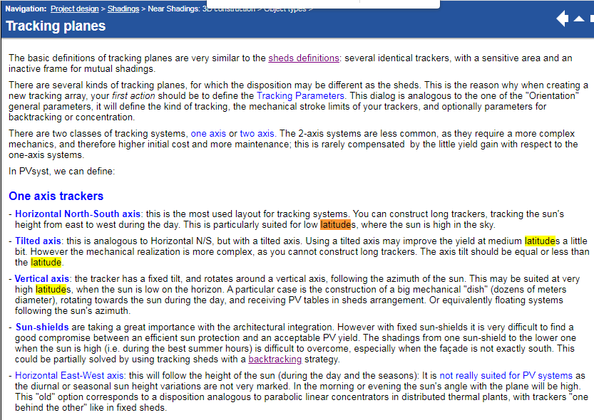
Good morning,
In the Help > Project Design > Shadings > Near Shadings: 3D construction > Object types > Tracking planes, in the last paragraph "Array of trackers", one of the sentences bothers me.
QuoteThe mutual shadings are related to the pitch and the width of each tracker, or more specifically to the ratio width/pitch, which is more or less represented by the "Ground Coverage Ratio" GCR. The lower GCR, the higher shading losses.
I think it should be, the higher GCR, the higher shading losses (i.e. lots of ground covered, more shadings), or retrospectively the lower GCR, the lower shading losses (i.e. low GCR -> not much ground covered by collectors -> i.e. lots of space between trackers -> less shading)
high coll. width -> more shading -> higher GCR = width/pitch
high pitch -> more space between coll. -> less shading -> smaller GCR = width/pitch
Hence, the higher GCR, the higher shading losses.
Is that correct? Let me know if I'm wrong


Sunny Boy JP (for low voltage systems)
in PV Components
Posted
Hi, thanks for the tip Michelle, I never thought of checking the "Background Knowledge" on the SMA website, you get the Efficiency tables in so much more details than on the regular datasheet, and this for all models of inverters . This is really useful to edit the efficiency curves when creating a new inverter in the PVsyst database.
Regarding the 202V voltage output, I just realized that this an inverter for the Japanese market... (where their standard single phase voltage is 202V and not 230V).
Hence the "JP" for Japan, and the JIS efficiency.
I thought it was a really good inverter for low voltage inputs (MPP range 60-450V), I struggle to find SMA inverters accepting short strings with low voltage.