


jammyc
-
Posts
52 -
Joined
-
Last visited
Everything posted by jammyc
-
Hi, Basically a repeat of this (now old) request: https://forum.pvsyst.com/viewtopic.php?f=3&t=2452&hilit=batch+zone Currently if a layout is defined as sheds using array zones, the 3D shadings parameters are not available to batch mode. It would be great if it were possible to change the array pitch, tilt (or azimuth, perhaps) in batch mode... It would significantly streamline, and make more accurate, the process of determining an optimum spacing. Thanks in advance.
-
Thank you!
-
Please disable (or provide an option to disable) system sounds creating a "Ding" when running batch mode simulations each time a line is completed as if the workstation is used for anything else it can be quite distracting! Many thanks!
-
Hi, Is it possible to change the charge/discharge power during batch mode? It looks like only number of parallel battery/rack strings can be varied Thanks.
-
Unless I haven't understood this and related threads correctly, this value is used for calculating transformer losses, which on a larger solar park are not insignificant! Granted they are (one hopes) small compared to generation, but they do reflect large sums of money, and it can be quite relevant when assessing proposals from manufacturers with differently rated inverters and transformers. So I take issue with the assertion that it of "weak significance"!
-
Hi all, How does everyone implement fencing when importing from Helios 3D? To date I've been manually defining them in PVsyst so I can create them as thin objects, but that's time-consuming. I've been trying to convert them in C3D/H3D into meshes (a task in itself), but when I import one it causes PVsyst to crash. (I think that's because they end up as being topologically identical to an open cylinder, rather than being a closed solid) Suggestions welcome! James
-
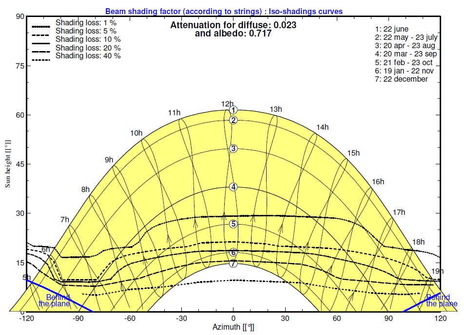
Hi, I have just run a simulation for a ~4MWp array, with the terrain model - including DTM and custom mesh-based objects - imported from Helios 3D and have found that if I switch on shadow casting on the ground terrain the shading model goes a little off-piste. Switching off the ground shadow casting, so including the array self-shading (with string effects) and other near-shading gets a much more sensible result. Oddly the hourly file seems to give a more realistic result, and the E_Grid values don't match the report! Any ideas? I think it's a bug, but I have emailed the PVsyst support crew copies of the project for a deeper assessment. Thanks, ... and with it enabled Iso-shadings without ground shading...

-
Hi Michele, I agree it would be very useful: While the voltages and power thresholds change, the same challenge of multiple stages of transformers applies in many other countries. I did request something similar - though not quite the same - in an earlier post (http://forum.pvsyst.com/viewtopic.php?f=12&t=1785) but it was a while ago and certainly worth asking again! In the meantime I've been calculating the losses for the network upstream of the first transformer manually, using the hourly output files. James
-
Importing/Reading Shade Objects V6.40 Bug Report
jammyc replied to gcantor's topic in Problems / Bugs
I have a similar issue with some - but apparently not all - of our older projects. However, I've just tried to save-close-reopen as you have, but that didn't work for me. The one I've just tried is quite an old project so it might be a compatibility issue. I have attached some screenshots to demonstrate. James Original project (Isometric view saved in our archive) New v6.40 (Top view to show the new arrangement)
-
Hi all, For large simulations it would be helpful if PVsyst could estimate simulation time. This would be both for the simulation "proper" and the shading tables. It wouldn't need to be highly accurate - perhaps by extrapolating time taken on steps completed so far - but if we set off a run it would be useful to know if it's likely to take a lunch break, an afternoon or a week! Primarily so we can abort and simplify if we need to before it's taken too long already. Of course, you can do this by hand already, but only if the simulation window hasn't frozen and you're on-hand to time it. James
-
Hi Andre, Just wanted to second Michele's request. If the shading calculation could be postponed until the rest of the simulation was run that would also be an advantage. I have also seen the same same secondary issue he has with large projects slowing down the rest of the program (most recently, a 50MWp park imported from Helios 3D which took several minutes to load the main pages, losses sheet etc); however just back from leave so haven't been able to check your suggestion. James
-
Hi Andre, That would be useful; I look forward to that update. In the meantime I've just come across a clear example illustrating the problem, which I thought I'd share to help you along: Transformer loss example Here we have exactly the same AC system; the only changes have been a reduction in quantity of module strings and reconfiguring the DC combiner boxes. The inverters and AC loss definitions have not been touched. However, the transformer iron losses have changed by 225W (or 1.9MWh/yr), which should not be the case since they will obviously be the same spec as before so the losses should be the same (and I would expect Pnom,AC to be the same too). Even if this is the expected behavious in terms of how you have defined the loss, it is quite counter-intuitive that the DC rating should have any bearing on this loss. Kind regards, James
-
The only parameter varied in the batch mode is the plane tilt (i.e. X-axis rotation / front-back angle from horizontal). It is varied after enabling the "Plane Orientation" tab of the batch mode setup. The baseline slope (Y-axis rotation) and azimuth (Z-axis) are constant and are set in the 3D near-shading model. In this (problem) case, the array baseline is sloped ~1-2deg EW due to the terrain, and faces due south (azimuth = 0). This works fine when the baseline slope is zero (or at least it appears to). If the baseline slope is non-zero, I think the problem is that the normal to the plane doesn't have the same azimuth / slope as the "nominal" aziumth / tilt.
-
Hi, I have a ground-mounted site with a very slight (varying 1-2degrees) E-W camber/yaw (Y-axis rotation). My client has asked me to run a parametric study on the array tilt angle, with a constant pitch (i.e varying the shading angle). I've done this several times before with zero camber on other projects but this time the simulations (except the first which matches the model) are failing with the error "Line :SIM_xxx The orientation of the collector plane for shadings doesn't match the one defined in the "Orientation" parameters of the PV array. Simulation not executed !" I think this is due to the rotation in the Y axis causing a difference between the array definition tilt and azimuth (e.g. 10, 0) and the actual incident normal tilt and azimuth (~10,5.7). Am I doing something wrong - has someone else got this to work? Or is it a limitation of the batch options? I feel like it should work so apologies if I've missed an obvious setting somewhere! If I do the same without the tilt it's quite happy. Thanks, James
-
Hi, I have noticed that PVsyst appears to take transformer losses as a % of the array (DC) STC output rating, rather than a % of the park AC rating as implied by the documentation. As an aside, as well as clarifying this situation, since the value is stored as a % it would helpful if it had sufficient accuracy to translate values specified in Watts back to their original figure. For example, when basing losses on generic transformers sized to EN50464 loss classes, we get questioned when instead of P0=3,500W, we see P0=3,424W in the report. James
-
Hi, I keep getting an error which causes PVsyst to fall over. "PushVar Error: Variable Stack full, Stop program !" I am not doing anything I wouldn't normally do (as far as I know) and it's the latest software version (v6.35). I've not spotted any patterns. On this particular project I've spent most of the time in the 3D shadings model so it's mostly happened there but the error also happens on the System sheet. Any ideas? James
-
Hi, Sometimes PVsyst's display of long thin objects (e.g. a hedge 700m long along the edge of a large field) gets a little confused at certain zoom levels. The shading calculations seem to be fine, just the visual display; sometimes the colour view also works okay. Similarly distortions can occur on particularly large projects. These often then overspill the display area on the report. While I'm at it, for big projects option to disable the perspective view (i.e. a simple isometric view) would be easier to work with / navigate at times, particularly when zooming in on the far end of a park some way from the origin. Thanks as ever. James
-
Hi, For scoping studies / optimisation where there is an existing load on-site and the client is considering east-west systems it would be helpful to be able to combine the multiple orientations and unlimited shed Orientation option. Obviously it can be done in the Near Shadings model when we've settled on the parameters but that doesn't lend itself to batch mode (i.e. time consuming) while using the plain multiple orientations loses the shading effect and calculating unlimited sheds separately means the export/self-consumption fraction won't be correct. Thanks, James
-
Hi, I have been wondering for a while why PVsyst appears to say the Meteonorm data is v6.1 when there is a more recent v7.0 available. However, it has become relevant as we are considering purchasing the full MN7 package if there turns out to be a significant difference. Can you please clarify which version (and which underlying dataset) PVsyst uses? Thanks, James
-
Slightly off-topic, but can you elaborate further? We are very interested in this topic and have looked at a number of plugins for PVsyst - such as Helios3D - but perhaps your extensions will do what we need?
-
Hi Vijay, I have similar requirements and have requested this already in the Suggestions sub-forum: http://forum.pvsyst.com/viewtopic.php?f=12&t=1785 In the meantime you can manually calculate the impedance as a % loss at STC load and input that. It does make for an odd parameter in the report (since PVsyst tries to work out what cable/length that equates to) which you may have to explain to your client but the result stands. James
-
Perhaps you could approximate it with soiling factors if the whole array is "hidden" by glass? It's not perfect, for example the angle of incidence would not be taken into account, but better than nothing if you calculated a worst-case loss factor. Older releases of PVsyst v6 used to allow you to specify most shading objects as "thin objects"; you could then set the thin object factor to an approppriate value that you had calculated which would then reduce the shadow effect accordingly. This allowed you to deal with glass parapets surrounding balconies and the like where only part of the array was affected. I am not sure that this was intended behaviour, however, and it seems that this was removed in recent releases with thin objects being restricted to objects which are, um, thin! For example, cables and handrails. You might try to get hold of an older release, but I doubt it would be supported and obviously more recent versions have had bugs fixed etc. James
-
Hi Andre, Thanks for looking into this and adding on to your ToDo list! Not sure if this makes more or less work for you, but if possible it wouldn't be unreasonable to keep the current setup as well as limiting export at the injection point: The most relevant option - at least in the UK - will depend on the network operator's requirements re how you maintain the limit. Sometimes we're required to use inverter settings, i.e. how PVsyst currently models it, other times we can look at the injection point (in which case we currently have a post-simulation processing stage). James
-
Might it be possible to add a "Detailed computation" for the AC losses similar to that for the DC? For example, on a large solar park: - A x central inverters per external transformer connected by LV cabling per inverter (akin to "string module connections" in DC terms) - B x MV distribution circuits with C x transformer kiosks ber circuit ("connections to main box") - Final connection to provider ("main box to inverter") - Transformer losses specified per transformer and multiplied by number of units With this, the voltage at each level could be specified so it could also be applied to smaller parks and building connected installations with string inverters and an LV distribution system connected to a single transformer (or no trafo at all!) at the point of connection. Also, can we have parallel cables as an option for all the sizing calculations? I know the final calculation needs to be done separately to local standards but clients do give you a funny look when your model says 1000mm2 cable (not readily available where we are, compared to 3 x 240mm2 which is off-the-shelf). I appreciate that the effect is not huge and there are workarounds (e.g. calculate the STC loss fraction manually) but given that it does affect the PR value as used in performance guarantees and O&M contracts it would give clients a lot more comfort to see values more closely representing their system. (It is, also, time consuming at present). It would of course be preferable to have the option to define each circuit separately but I think this is a reasonable compromise that closely follows the existing structures. Thanks!
-
Another vote for the import ability! As an intermediary option, you could make the specification for the Shadings Scene or Helios3D import files open source, as currently we're forced to look at rather expensive proprietary providers. You've mentioned before that at least some parts of the program are written in Delphi and I for one would be quite willing to try homebrewing some import code while you sort out the details. Obviously we would then take on the risk of inaccurate input. Indeed, this was something I considered for my dissertation several years ago! James PS - Off-topic but really pleased with today's update to the Module Layout page, thank you


(resized).jpg.cc4f803fb1d4190b6d68b8724ce663b7.jpg)
