


Michele Oliosi
-
Posts
747 -
Joined
-
Last visited
Posts posted by Michele Oliosi
-
-
Generally, smaller (rooftop) installations are more complex in terms of shading than large, regular ground mounted systems. In the latter case, strings are usually distributed on one or two large tables, and this pattern repeats, which makes it possible to use the “partition model” which is a simplified model to estimate electrical shadings.
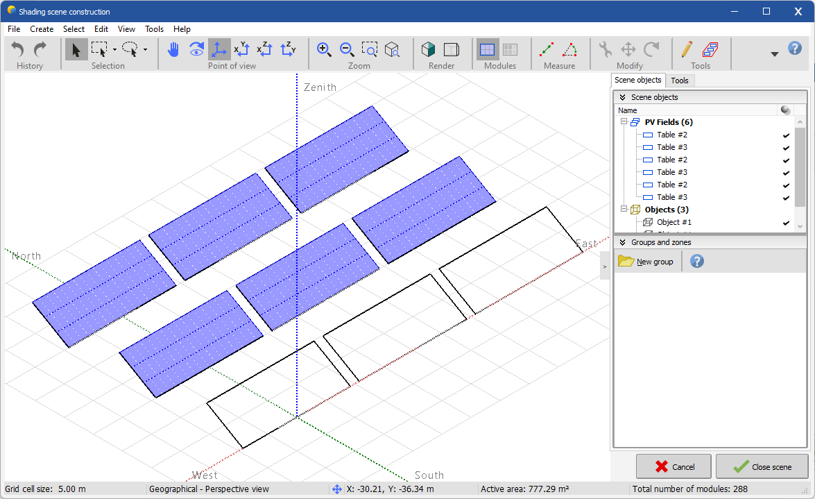
In the former, smaller rooftop case, it is best to use the most detailed modeling of electrical shadings. This is the module layout option, which necessitates to determine exactly which module 3D model is connected to which string. Even though your system is simple electrically, given the 3D scene, shadings will have a non-trivial aspect and necessitate this more advanced calculation. You can see one such complex shading pattern in your first screenshot.
-
It is partially solved in version 8, which should release (really) soon. You will be able to define separate bifacial models, one for each fixed tilt or tracker orientation. However, dome configurations are not yet covered by this update. We will work on it for a future minor release…
-
Hello, the forum language is English, but if you send your query to support@pvsyst.com we will happily reply in French.
If this period is continuous within the interval of January 1st to December 31st, then you can use the following tool. From the project window, go to “Advanced simulation”. There you can change the start and end date of the simulation. If you then run the simulation by clicking on the “Run simulation” button in the “Advanced simulation” window directly, the correct dates will be set.
However, the method you suggest will also work, i.e., importing weather data that covers a shorter period (possibly with holes). -
Hi, not sure what you mean by using a CSV to build the 3D scene.
Could you send your project at support@pvsyst.com? We would then be able to look at the 3D scene.In any case, take a look at 3D scene → Tools → Backtracking management. There you can verify the backtracking parameters.
-
Hi !
Actually, you do not need to have an "array of tables" in the 3D scene to apply the bifacial model, but there are a few regularity requirements that have to be met:
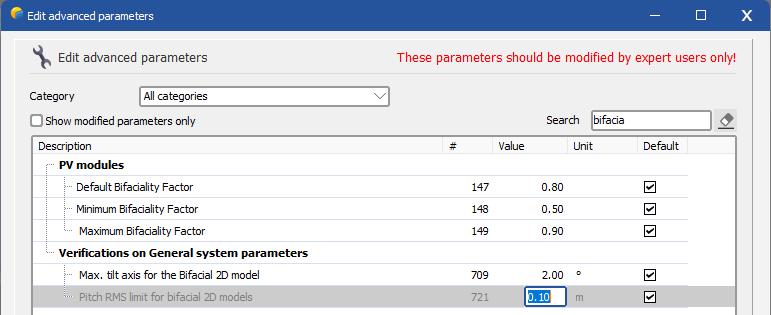
https://www.pvsyst.com/help/bifacial-conditions.htmHowever, it cannot be expected that you modify the pitch of your plant just to run the simulation. For that reason, it is possible to modify the threshold for the activation of this error. Since this error stems from the evaluation of the standard deviation on the pitch distribution, the threshold can be changed in the advanced parameters : Home window > Settings > Edit advanced parameters:

Please be aware that while this won't modify the results of the simulation, it will allow you to simulate a situation in which the bifacial model (which is a regular idealization using the average pitch and table size values) will not fully represent the complexity of the 3D scene. However, usually, unless you have a very strange setup, the error from this discrepancy is minimal.
-
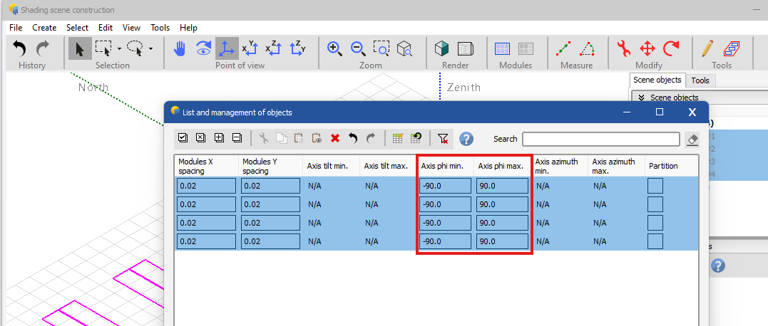
There is a problem with the trackers created by zones. These end up having +-90° of maximum and minimum rotation angles.
To correct this, once you created all trackers, you can either go to Tools > List and management of objects, or simply press CTRL+G in the 3D scene. There, you can find the column with the min / max phi and edit them to be compatible with the orientation.
-
@Loïs Masson Yes it is possible to use partitions with a non-rectangular PV table. Honestly, with non-conventionally wired modules such as the voltec ones, there are no other solutions with the current PVsyst version. Finding equivalent modules, to run the module layout calculation, and using that to adjust the results of the partition calculation, as suggested at the beginning of the thread, seems like a reasonable idea.
-
In all three cases, you should put X = 2, Y = 1. Indeed, you have at most one string per table. Y, for NS-axis trackers, should be the number of strings longitudinally. If there is a fraction of a string (such as in the case of half- or quarter-strings), you can leave Y = 1 as well.
-
yes you got it, x = 2 (because half-cut) and y = 3 (# of strings)
-
Can you also share the voltec module references ?
-
The partition tool is not really adapted to this kind of situation either. For irregular shadings, it tends to overestimate the losses.
I would suggest changing the parameter "Fraction for electrical effect" to about 20 %.
This will reduce the electrical shading loss so that it has about the same magnitude as the jinko modules. I did not go as far as setting a 10% fraction because it is better to be very conservative in this case. -
This is normal, since PR is defined normalized by the front-side POA irradiance (GlobInc) but bifacial modules can also capture light from the back.
The PR of bifacial projects is oftentimes > 1.There are more details on this help page: https://www.pvsyst.com/help/performance_ratio.htm
Regarding the negative Global Incident, this is also normal, because it accounts for the front side irradiance relative to the horizontal plane. If you just look at the front-side, there is more irradiance on a horizontal plane than on a vertical plane. This is of course more than compensated by the backside irradiance part of the loss diagram.
-
The Global incident will be negative if the orientation is worse than the horizontal fixed plane. I am not sure why, just from your text. Indeed, in principle, trackers should have a better transposition than a fixed plane.
It is difficult to answer just from the loss diagram and 3D screenshots. Could you export your project and send it to support@pvsyst.com ? -
Did you try other distances? I don't see a problem because you show just two instances. At 4 meters there may be still a lot of impact from mutual shadings.
-
In your top question, the shadings are not exactly the same. Are you using the fast (relying on interpolations, which are sensitive to tiny rounding differences) or slow method ?
-
EW trackers here can follow the sun closely in the morning and evening. Instead, fixed tilt does not have a good orientation in the morning and evening.
-
-
Hi, this is a complicated question. The partition model is really ill-fitted to this kind of arrangement.
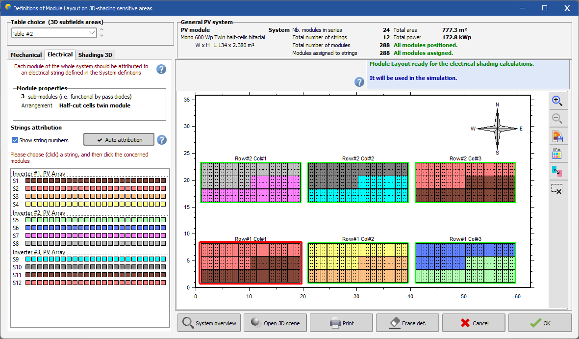
The best is to model this first with the module layout:
In this situation (GCR, tilt, climate, inverter layout, type of modules) this gives me about 0.9% electrical shading losses. If I then wanted to replicate this in the partition model, it is best to proceed by trial and error.
Here defining 3 partitions in Y and 1 partition in X seems to work best to replicate the same amount of electrical shading losses. I tried first Y = 6, but the electrical shading losses were too small.
In summary, it is hard to define how to partition in this kind of situation, and it will depend a lot on many factors. It is best to check with a simplified layout in the module layout to make sure that the partitioning gives a good amount of losses.
-
Half-cut cell modules in portrait, strung in U (2TU) have:
- Partitions in y = 2, partitions in x = 1
For wider tables which are 2 strings across (26 = 2*13) still strung in U:
- Partitions in y = 2, partitions in x = 2
https://www.pvsyst.com/help/shadings_partitioninstrings.htm -
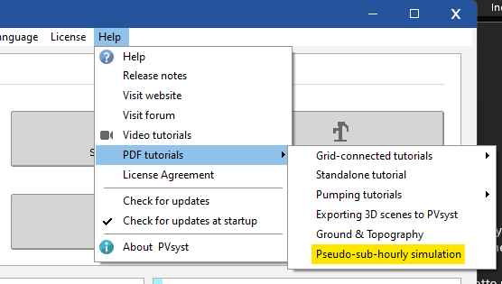
Please read the highlighted tutorial..
-
Hi,
First, please understand that the partition model is an approximation that is well-defined in the case of simple rows of tables or trackers, with topographies that are quite regular.
In the case of other irregular situations, such as your figure 6 and the discussion about figure 4, the usual rules from the help page do not apply. You can choose to use the partition model differently than the intended partitioning, as you did, but this should be done very carefully. I think you are correct in decreasing the number of partitions when shadings are irregular; this is the more conservative approach.
Regarding figures 3 and 5, I agree that a partition in X is missing. Indeed, it should be X = 2, to differentiate the different strings. We will correct these images asap.
Regarding figure 1, I do not agree with your comment. Indeed, in the case of regular rows, the effects of by-pass diodes and diffuse fraction accounted together are best modeled by Y = 2. Even if there are multiple strings on a given MPPT, as long as they are all shaded in the same way, the effect is the same as having one string by MPPT.
-
This is not possible directly from a single PVsyst simulation (which is in hourly steps). But you can run multiple simulations to approximate sub-hourly results. In version 7.4.8 we added a tutorial for this procedure because it is a bit technical. You can find this tutorial here:
-
You have 1% "climate change" this parameter will make P50 and E_Grid(Sim.) differ. It represents the fact that the weather data used for the simulation is not representative for the P50 (e.g., the P50 may change in the future, or has changed since the data was recorded).
-
If you look at the irradiance on the plane (GlobInc) you can see that it is fairly similar throughout the year. The chosen orientation is giving a push to the production in winter.
PVsyst 8 - Subhourly new features
in Simulations
Posted
If you import sub-hourly data you can then use that as an enhanced MET file in your simulations.
Here is a help page that breaks it down: https://www.pvsyst.com/help/physical-models-used/grid-inverter/subhourly-clipping-correction.html