
Michele Oliosi
-
Posts
793 -
Joined
-
Last visited
Everything posted by Michele Oliosi
-

Unexpected Differences Observed in Results - PVsyst v7.2.11
Michele Oliosi replied to kjs55's topic in Problems / Bugs
Hi, I am not sure whether you have already, but you can drop us an email at support@pvsyst.com, ideally including your project and the two differing variants / reports. We will then be able to review what is going on. -
At the moment IAM losses are automatically included in the irradiance contributions. Therefore, measurements (e.g. with a pyranometer) may differ from (GlobBak + BackShd). As you mentioned in another topic, we will think about adding an IAM loss estimate so that we can remove it from the PR normalization.
-
Thanks for the feedback !
-
Yes and yes. If you leave 25° & 25°/1000W you will get 50° at 1000W : 25° is the base temperature. If the inverter is cooled efficiently then yes you can put 0°/1000W as the proportional increase.
-
The system definition should match the entirety of the scene. To be accurate the partial shadings tool is really to be thought of as a subset of tables that will represent all tables in the scene for the purpose of shading calculations only. It does not allow to perform a partial simulation (over just part of an array). Indeed, currently the tables do not change colour. We need to fix that.
-
Bifacial: importing measured rear side irradiance
Michele Oliosi replied to johank's topic in Suggestions
Hi, thank you for the feedback ! At the moment PVsyst would not be able to use this information for the simulation, contrary to the POA irradiance, which can be converted into GHI and DHI and therefore be used as input for the simulation. We hence still need to address the question of how to use this information. However we will keep your feedback in mind for an overhaul of the measured data comparison tool. This would be a simper use for this kind of data. -
How is the PR (Performance Ratio) calculated ?
Michele Oliosi replied to André Mermoud's topic in Simulations : results
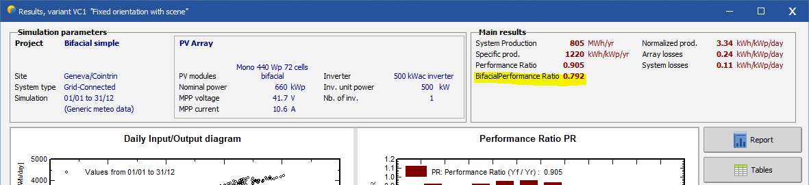
Following the update of IEC 61724-1:2021, since version 7.2.13 you will find a bifacial performance ratio in the results summary window. This bifacial performance ratio is computed as: PRbifi = PR / (1 + (GlobBak + BackShd)/(GlobInc)) (see https://www.pvsyst.com/help/performance_ratio.htm) Note that this may not correspond to notes 1 and 2 of §3.20 in the norm IEC 61724-1:2021, since it does not include the bifaciality factor. It is instead based on a literal interpretation of the IEC 61724-1:2021 §3.20 main paragraph.
-
Hi, Yes the standard PR in PVsyst is normalized with respect to the frontside irradiance only. Since version 7.2.13 you can find an adapted bifacial PR in the results summary. See https://www.pvsyst.com/help/performance_ratio.htm
-
Since version 7.2.13 you will find a bifacial performance ratio in the results summary window. This bifacial performance ratio is computed as: PRbifi = PR / (1 + (GlobBak + BackShd)/(GlobInc)) (see https://www.pvsyst.com/help/performance_ratio.htm) Note that this may not correspond to notes 1 and 2 of §3.20 in the norm IEC 61724-1:2021, since it does not include the bifaciality factor. It is instead based on a literal interpretation of the IEC 61724-1:2021 §3.20 main paragraph.
-
PV Array Characteristics/ At Operating Condition (temp)
Michele Oliosi replied to Detroit Solar's topic in PV Components
Sorry my answer was not so clear. In the simulation, the temperature of the modules at a given hour is taken into account automatically of course. Meaning that if the modules at a given hour are hot, then they will be less efficient. (This is not affected by chosing 22 or 50.) This is what I meant by follow the one-diode model. You can find more information here https://www.pvsyst.com/help/pvmodule_corrtemper.htm The second part of my answer just meant: there is nothing special about "22°" in particular, and the choice of "22°" in particular in the project settings dialogue will not affect the simulation. It is just an example of a characteristic temperature (which in fact seems quite low in your case, maybe a choice due to low ambient temperatures). -
The correction should come out in the next or in two patches time.
-
Hi, You should consider using the "Aging tool" that you will find in the advanced simulation window. This will take into account the yearly degradation, basically what you have done in excel. It also allows to access to the degradation loss window, which will give you more information on the aging loss. Note that you can only simulate a single year with the meteonorm data you have, because what meteonorm provides (in PVsyst) is a statistics-based synthetic year, similar to a typical year, that is not a real year per se. This is indicated by the year 1990 in PVsyst. You can simulate the aging through 20 years of simulations using the meteonorm data, but the same weather data will be used every year, which is not really realistic. Real years will be subject to year-to-year variations. Therefore you should maybe look into getting real time-series data for 20 years. One option (though it may have only 12 years or so) is: Main window > Databases > Known format : choose "PVGISv5 hourly time series direct import" in the drop down menu. This will download a number of time-series files, which you can then use in the aging tool above. NB: the aging tool is not available for stand-alone systems yet. In order to use it you should redesign your system as a grid connected one. However please first consider the stand-alone system to get advanced information on the battery sizing.
-
Hi, Short answer: yes, but* PVsyst still works with a single average orientation for the transposition of the irradiance and incidence angle modifiers. However the 3D scene may contain trackers with various orientations due to topography. The shading losses will be computed accurately using the 3D scene. Finally the bifacial model is usable only if the orientation differences are small. Note that even in that case, the bifacial model will consider a fictional perfectly flat array for the backside irradiance computations.
-
Simulation based in measured global on plane. Tracking
Michele Oliosi replied to tecnun's topic in How-to
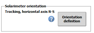
It should be possible in the current version of PVsyst. In the custom import window, you can choose the orientation when you have chosen GPlMeas as a variable: Please let us know if you have any trouble.
-
Hi, The $01 is due to a bug, the correct text should indicate something along the lines of: "increase according to global irradiance on the plane of array". Basically, it means that the temperature will increase according (proportionally to) to the irradiance on your field, i.e. the power generated. The value to be inserted is the increase in degrees per 1000 W/m^2 of irradiance. The question of outdoors or indoors is really a question of temperature control. In this case the inverters are probably subject to the ambient temperature, so ambient temperature / ambient temperature with shift are both reasonable choices.
-
Hi, Thanks for the feedback. Since this would be a very big change, a complete sub-hourly simulation is not on the horizon yet. However: you can already import sub-hourly meteo data, and use it to perform a hourly simulation we are currently working on a solution allowing a partial use of the sub-hourly data to address clipping losses As johank points out there are not that many data sources just yet.
-
Hi, There seems to be a bug in the window that we need to address, we will raise a ticket on this. In the meantime the only option would be to use the automatic filling tool "Auto attribution". As long as the lower (the ones you can see) are correct, you can assume that the others are filled along the same pattern. An example below:
-
You are right, they are not really the same. We will remove the "transverse incidence angle" mention.
-
Hi, First of all: I greatly encourage you to update to our latest version. There have been many improvements and bug fixes since verion 7.2.3. Possibly you will encounter less problems on an updated version. Second, the subarrays on the inverter SUN2000-215KTL-H3 seem to be okay, however, you first have to correct the issue (written in red) with the subarrays on the SUN2000-185KTL-H1. Indeed this needn't be a blocking message, and we will raise a ticket to address this issue.
-
Manually changing meteo data not working CMSAF
Michele Oliosi replied to Niels's topic in Meteo data
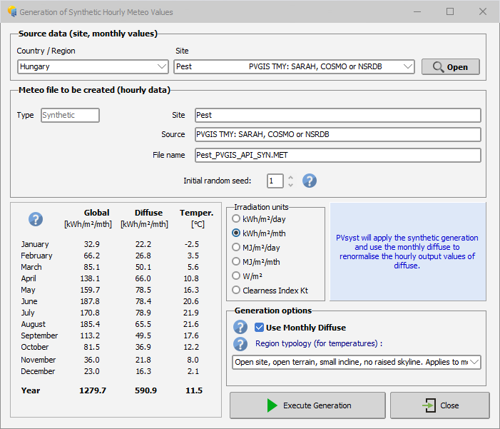
Hi, You need to regenerate a new .MET file that corresponds to the monthly data (see the example screenshot below). In the site drop-down menu, you should find the site you have saved with modified values. You should then use the new .MET file for the simulation.
-
PV Array Characteristics/ At Operating Condition (temp)
Michele Oliosi replied to Detroit Solar's topic in PV Components
Hi, During the simulation, PVsyst considers the current temperature of the PV modules, which may be any value. The production takes into account these temperatures differences based on the one-diode model. The specific value at operating conditions (for you 22°) is just an example value, it doesn't really affect the simulation per se. -
Split GlobBak into GlobBakInc and GlobBakEff
Michele Oliosi replied to johank's topic in Suggestions
Hi Johank, Thanks for the suggestion, we'll be looking into that.! -
I have added this feature to our ticketing system to be evaluated. Thanks for the feedback !
-
Hi, The easiest way would be to do a bifacial simulation. Whenever the bifacial model is used, you have access to the output variable: global on ground, which computes the average irradiance on the ground taking into account the shading from regular rows of tables or trackers. You can choose this variable in the hourly variables.