


Michele Oliosi
-
Posts
754 -
Joined
-
Last visited
Posts posted by Michele Oliosi
-
-
You can check this topic as well the issue is similar
-
@JaviBrave Here is a quick gif of the procedure, hope that helps !

-
Hi, you should rather put 2 rectangles in X. It is not really possible to define 1.5 string per table, but since (I assume) all your strings will be submitted to similar regular and longitudinal shadings, the distinction between the full and the half string will not matter for shadings. They will probably be shaded in the same way.
-
Actually PVsyst will apply both by default. The nominal active power limitation by the inverter is automatic.
The question "limitation applied at" "inverter" or "injection point" refers only to the supplementary grid limitation. The difference is whether or not the losses between inverters and injection point should be taken into account to raise the limitation a little bit at the level of inverters. -
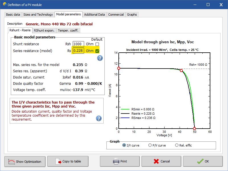
Basically if you are using a PAN file not from the PVsyst database, sometimes the module parameters have not been assigned following our default procedure.
Whenever we apply aging, the module parameters have to be recomputed (this time we use adapt the parameters automatically), which may lead to some discrepancies.
It should be good practice to check all module parameters beforehand.
https://www.pvsyst.com/help/pvmodule_parameters.htm
https://www.pvsyst.com/help/pvmodule_rserie_rshunt_determ.htmYou especially want to look at the page:
-
Thanks @dtarin
@Nader Shaheen, regarding the white roof additional generation potential, you should define a higher albedo in your bifacial model definitions ("bifacial" button in the system window, appears once bifacial modules are selected).
Themal parameters won't change between bifacial and monofacial, you can use the presets to fit your case. For module quality you usually don't need to do anything but leave the default, unless you are using degraded modules. Finally ohmic losses just depends on your cabling. A more visual way is by defining cable lengths in the "detailed computation".
-
Hi @ayoub96, no you are not missing details I think. Can you give some sample of your values and sums ?
-
Hi can you give some examples on the differences you find ?
Indeed you may be in a situation that has almost the same angles and therefore leads to slightly different results.
The PhiAng is the angle used for the whole time step, so in principle both results should match. Some other geometry factors may be at play: do you have exactly the same geometry of the tables ? (Module spacing, frames, etc) and are you using the same shading calculation ?Finally, the diffuse shadings for trackers are done a bit differently, so comparing values after the shading loss may not lead to the same results, albeit the results should be close.
-
Dear Nicolas,
Your understanding is correct. The results at the end of the simulation are for the whole system.
No at the moment, is not possible to get results for each orientation as a single simulation output. -
There may be a bug indeed. You can send us your project (export it via the main window > File > Export projects) for review.
You can also try the following: within the 3D scene there is Tools > Orientation management, which can allow you to assign tables to a specific orientation. -
Dear IgLoo, unfortunately no. You can change the report settings but at the moment TArray is not an option for that table.
I'd add that since TArray may widely during the day / night, the monthly average value may not be very informative.
-
Yes, it technically is less accurate to modeling things with one orientation instead of having all orientations of your tables. But unless the RMS of the differences between planes is extreme (e.g. 20°) there should not be a huge impact.
-
Is it a PAN file provided by a manufacturer or a module from the database ?
You can check whether the parameters do not have any of the default checkboxes checked (one of them is already good). E.g.
If you are not sure you can send your PAN file to support@pvsyst.com. Personally I am not quite confident about giving good advice on modules, but my colleagues should help with that.
-
Looking at your data it seems that the irradiance values are too high.
First of all please make sure that all the parameters of the import are correct. Try to double check all the units so that they match the units in your measurement.
If in trouble you can also assign a multiplier to each value.
I see you have a time sihft issue, I'd recommend setting the time shift (30' + or -, I am not sure of the needed sign) in the conversion protocol as well. -
Hi, you may be interested in https://www.pvsyst.com/help/batteries_modeldescription.htm
You can define two different types of initial state of wear
-
If you need to distribute strings over multiple tables, you can only do that with the module layout.
At the moment we do not support partitions on multiple tables.
I would advise the following: run the module layout once to get an estimate of the electrical shading factors. If your scene is too large, you can create a smaller scene with similar shadings.
Then when using the partitions, start by defining 100% for the electrical effect fraction. If you see that this overestimates the shadings compared to the module layout, you can reduce the fraction. Apart from that there is no failproof way to define the electrical shading fractor whenever you have both regular (row-to-row) and complex (e.g. trees) shadings. -
Please double click on fields #2 to #9. In your system summary you can see that no orientation was defined for them: they have orientation #-1 instead of #1 or #2. So please open the objects and select the relevant orientation.
-
Ok then that is likely the reason. The PR is basically a ratio between yield and incident irradiance.
These values are different at every hour. Now, you should remember that the ratio of averages is not the average of the ratios.
The correct way would be to sum the yield (E_Grid) and average the global incident irradiance (GlobInc) separately and then recalculate the PR based on the two resulting values. -
On the main window, try going to File > Reload databases.
As a second point, please check that coordinates do match closely.
Let us know if either helps. -
Can you explain your calculation for the monthly average PR ?
-
At the moment you cannot set different strings on the same MPPT within PVsyst. However you could modify the inverter and add an extra MPPT. As long as you are careful with the "power sharing" configuration, it can be a good representation of your system.
-
At the moment the workaround is to switch directly to "by modules". Adjust the spacing. Go back to "by summits" and redesign the polygon.
I have submitted a ticket to improve the functionality at some point in the future. -
I see, I will check whether we can create a similar functionality in the newer PVsyst as well.
-
Another point that may be at play: the module parameters have to be recomputed to be able to apply the degradation. If you are using a module that doesn't have standard one-diode parameters to begin with, once the aging is applied, they may change due to the recomputation of these parameters.


Power limitation in both, grid and at inverter level
in How-to
Posted
Ah I see, if both are different from the nominal power of your inverters you can either: