

Stéphane Metz
-
Posts
112 -
Joined
-
Last visited
Posts posted by Stéphane Metz
-
-
Dear Raad,
This error does'nt come from PVsyst, but seems to come from PVComplete.
Please contact PVComplete Support for assistance with this issue.
S. Metz
-
Hi Mohammed,
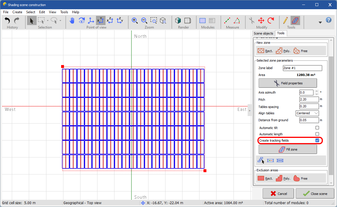
Just click on "Create tracking fields" and fill your zone:

-
Yes,
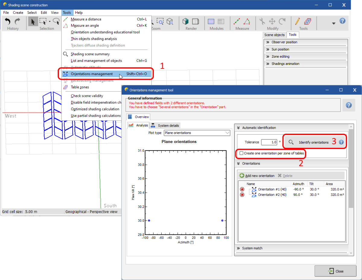
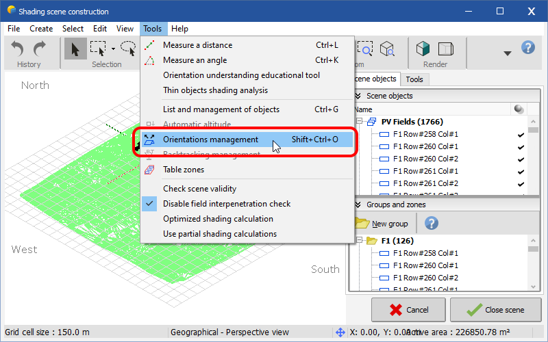
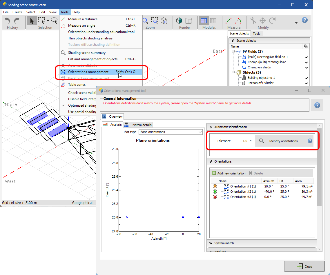
This is due to the zone, open the orientations management tool (1) in the near shading scene, uncheck "Create one orientation per zone of tables" (2), and run an orientations identification (3). Now you'll have 2 orientations, one East, and one West:
-
Hi Mohammed,
Indeed, PVsyst does not allow for the moment to fill the zones with domes. However, there is a workaround that can help you with your park filling estimate:
-
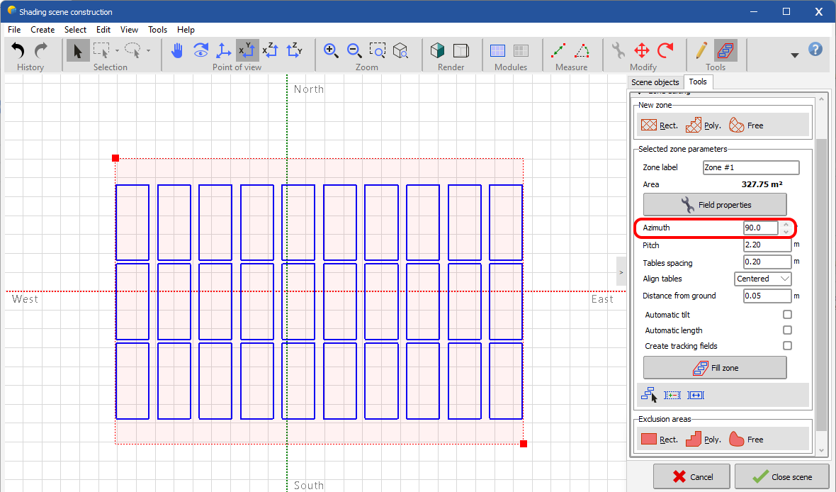
First create a zone as you did with an azimut of 90°:
-
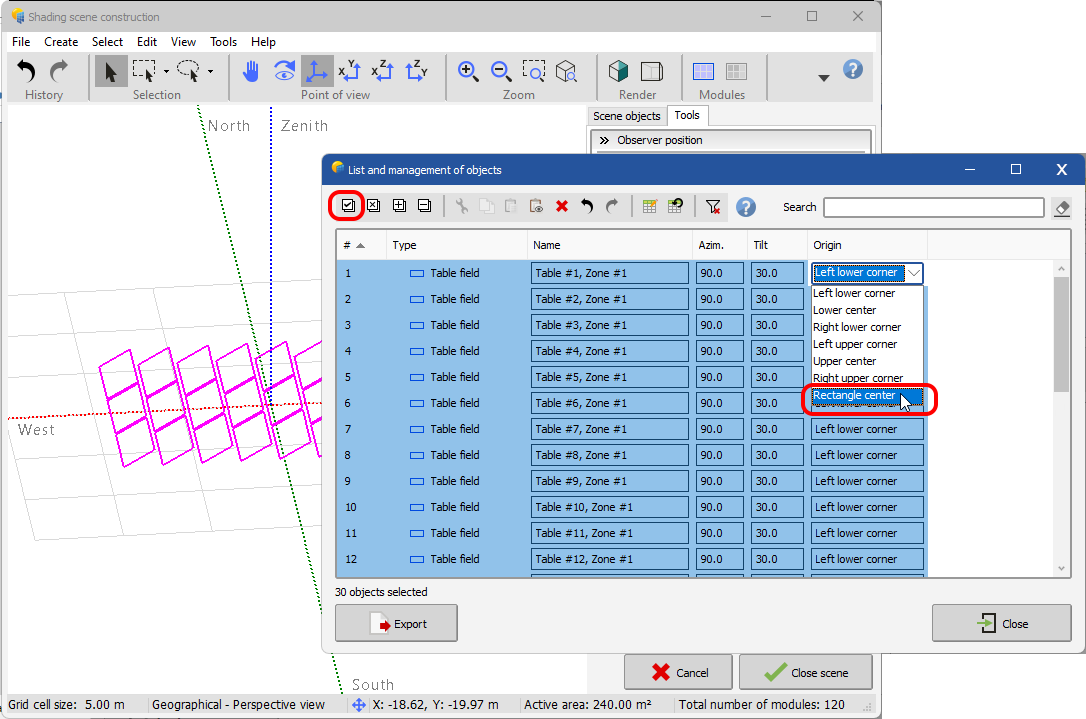
Then quit the zone editing tool, select all your tables, and change their origin with the advanced selection tool (CTRL+G):
-
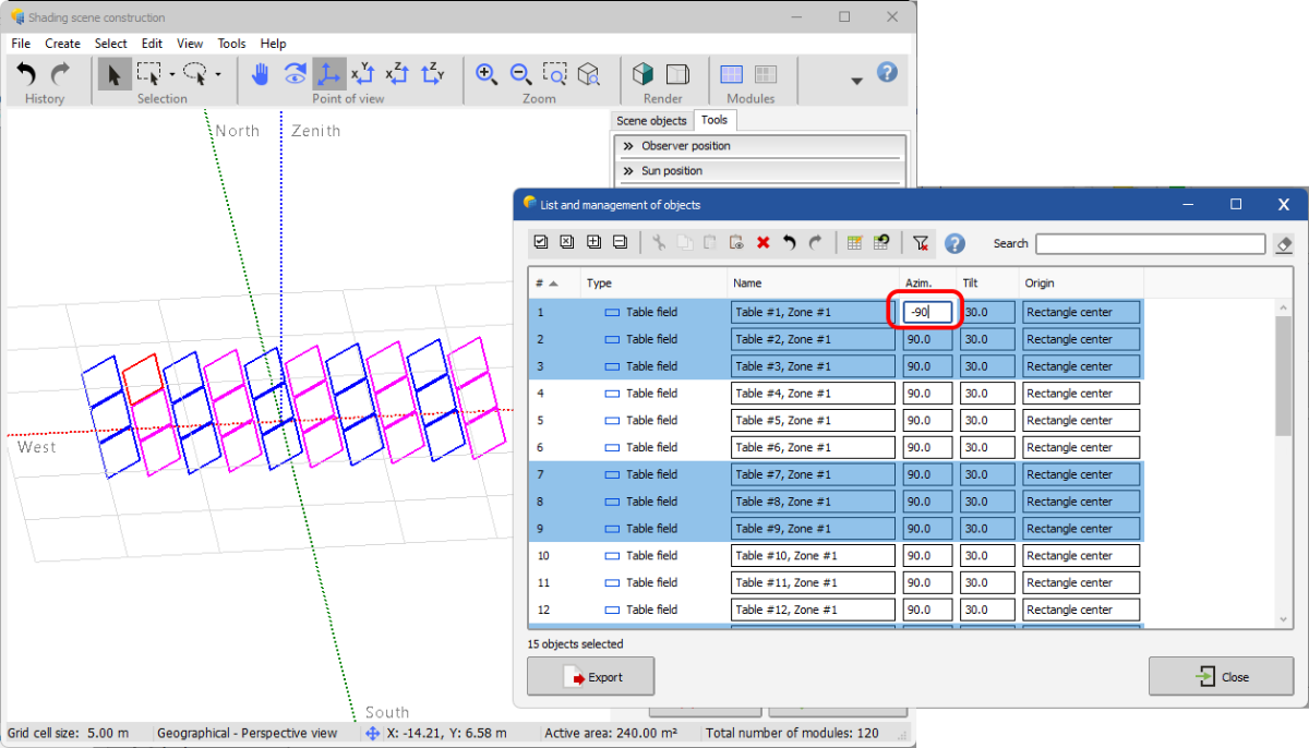
After select only the tables you want to rotate in the opposite orientation (here East), and change their azimuth to -90°:
-
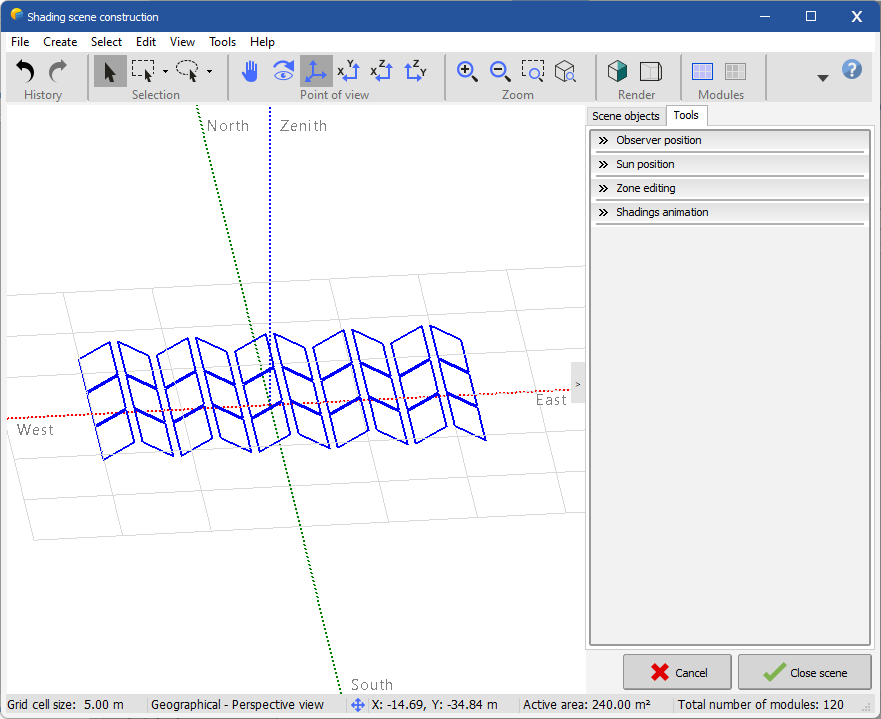
The result corresponds to East-West "domes":
Hoping to have been able to help,
Stéphane M.
-
First create a zone as you did with an azimut of 90°:
-
You're welcome!
-
Hi Salvo,
Currently it is not possible to mix fixed panels and trackers in the same variant, this functionality will be available in the next major version of PVsyst (V8.0).
Regards,
S. Metz
-
Hi @VUG,
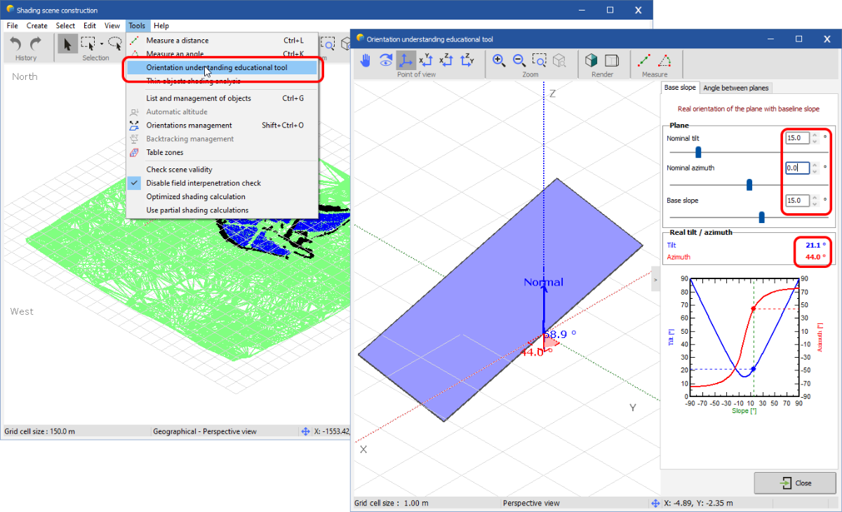
Your PV fields follow a ground slope, this introduces baseslope angles of each PV fields. That means that the real tilt/azimuth angles are not the same as the nominal ones.
You can use the orientation educational tool to better understand this concept:
So, in this case, PVsyst has detected several averaged orientations and grouped your fields there.
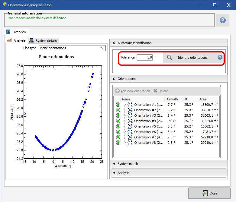
Note that PVsyst is currently limited to 8 orientations, you’ll have to deal with this constraint.To see the orientations, you can use the orientation management tool:
To limit the number of orientations, try to re-identify orientations with higher tolerance:
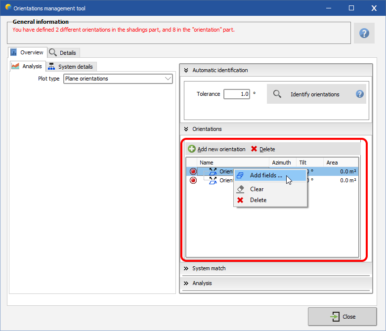
Or delete all orientations, create 1 or more new orientations and manually assign the fields, the averaged orientation will be determined automatically:
Note that the azimuth used in PVsyst is the real azimuth and not the nominal azimuth, because it is the real azimuth of the orientations that is used for the calculations.
Regards,
Stéphane M.
-
Hi @ZeynepB,
Unfortunately no, Sketchup remains the best alternative to convert DWG format to DAE or 3DS.
-
Hi @anish.silwal,
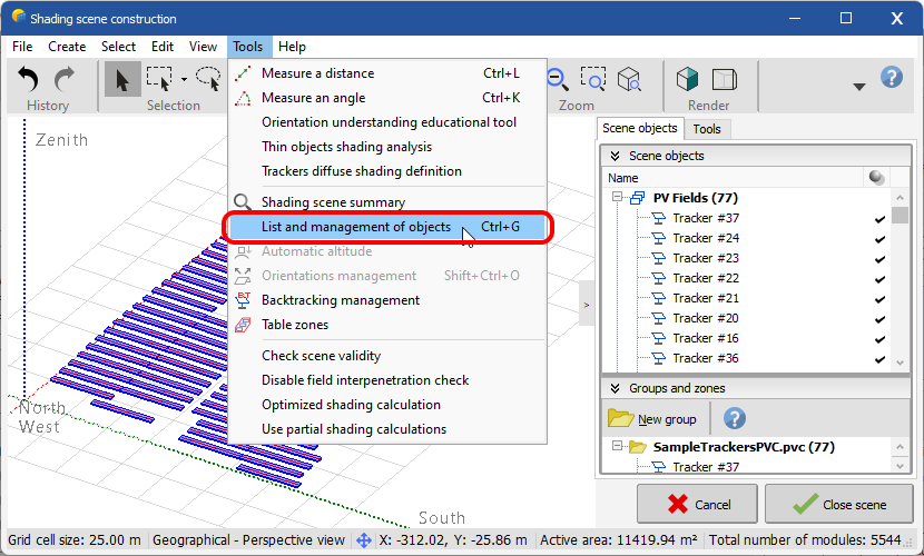
You can use the "List and management of objects" tool (CTRL+G):
Select the trackers you want to edit, and change the desired value in bulk:
Note: in you screenshot, trackers are defined "By sensitive sizes". Be careful, in this case it's not possible to modify these values, because they are relevant only when tables are defined "By modules".
S. Metz
-
Hi @laurahin,
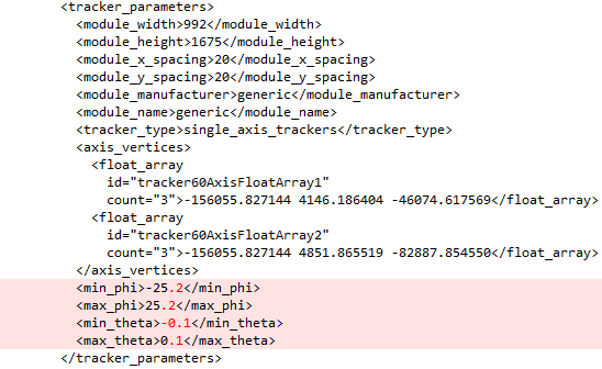
A user reported us a crash in PVsyst when he imported a PVC file containing decimal numbers for the phi and theta limits of the trackers like this:
This issue has been fixed in version 7.3.3
S. Metz
-
Dear @garf,
Indeed, it is only possible to mix orientations 1 and 2. This is a current software limitation. If you want to mix orientations 1 and 3 for example, you will have to switch orientation 3 to orientation 2.
FYI, we are currently working on version 8 which will remove a lot of this kind of limitation.
Regards,
S. Metz
-
Hi Awie,
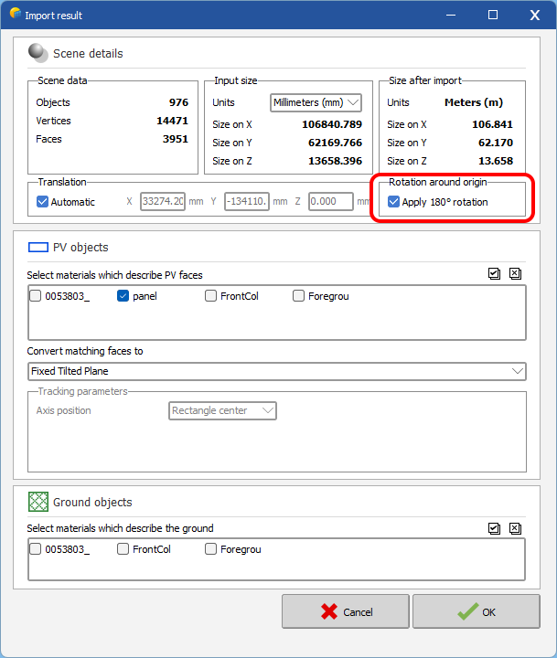
Well, I took a look at your 3D file. The problem comes from the new 180° rotation feature introduced in 7.3.3:
This doesn't work properly with PV objects. I opened an incident ticket here, it will be fixed in the next patch.
In the meantime, uncheck this box (it is automatically checked in the southern hemisphere), and manually rotate the entire scene 180° if necessary after import.
Thank you for reporting this problem to us.
Regards,
Stéphane M.
-
Hi @iulian.trisca,
Regarding your 2 points:
- This only happens if you haven't created any zones yet. This problem is also present in previous version. We will fix this for the next patch.
-
This is a display issue specific to Trimax Solar PV modules, it is also present in previous version. We will fix this for the next patch.
Thanks for bringing these issues to our attention.
Regards,
Stéphane M.
-
Hi Awie Botes,
You are the first to report this problem to us.
Could you send us the 3ds file at support@pvsyst.com so that we can reproduce the problem on our side?
Thanks,
Stéphane M.
-
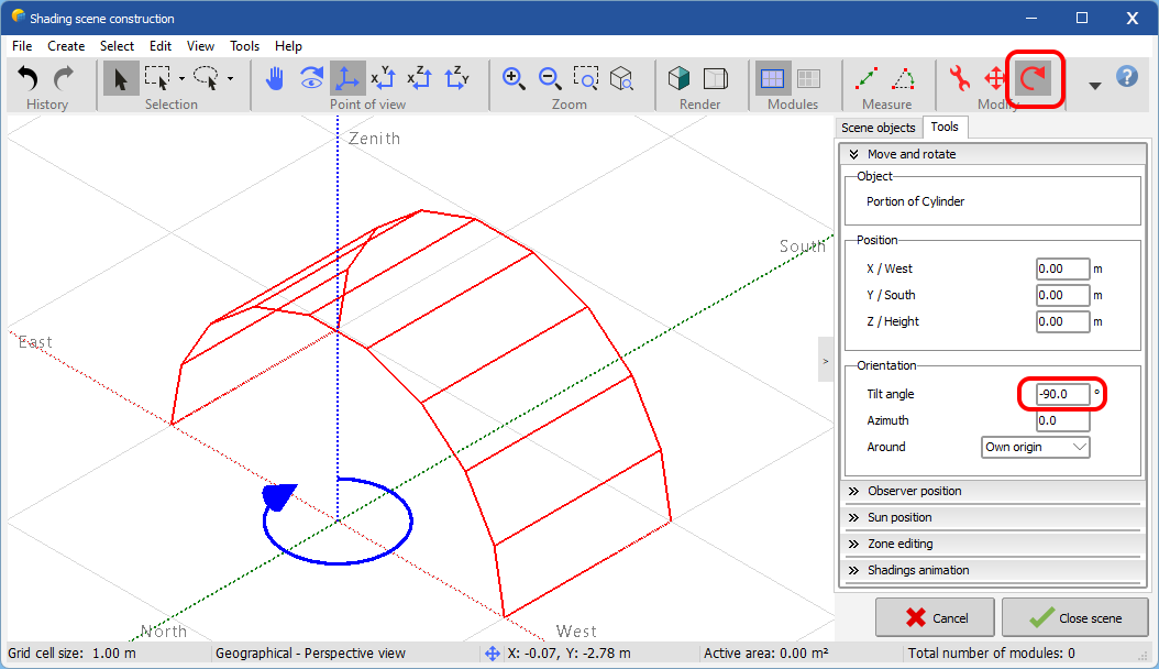
Hi Rachel,
You are right, tilt rotation is not intuitive in this case. But you can also access this parameter with the rotation tool:
Regards,
Stéphane M.
-
Hi @C. Amorevole,
Your problem is a frequent case in PVsyst, since the PV tables follow the slopes of the ground. You must define one or more so-called "averaged" orientation(s).
From the 3D scene, open the orientation management window, and launch an automatic detection with a large enough tolerance to obtain the desired orientations:
You can also manually create your orientations if you wish (more details here).
After creating the orientations in the 3D scene (8 at most), you will have to harmonize them with those defined in the system and assign the subfields to these orientations.
-
Hi hcolin,
Indeed, the value is limited to 100. It is an arbitrary value considering that beyond this value, the area is no longer really realistic.
Unfortunately this value cannot be directly changed, but I can forward your request to the DEV team. For our information, what values would you have liked to put?
Regards
-
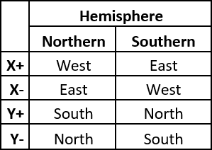
Dear Muhammad Zubair Ahmed,
The 180 ° rotation is due to the location of your site (southern hemisphere):
You can find more details about the PVsyst reference system in our help: https://www.pvsyst.com/help/index.html?global_referential.htm
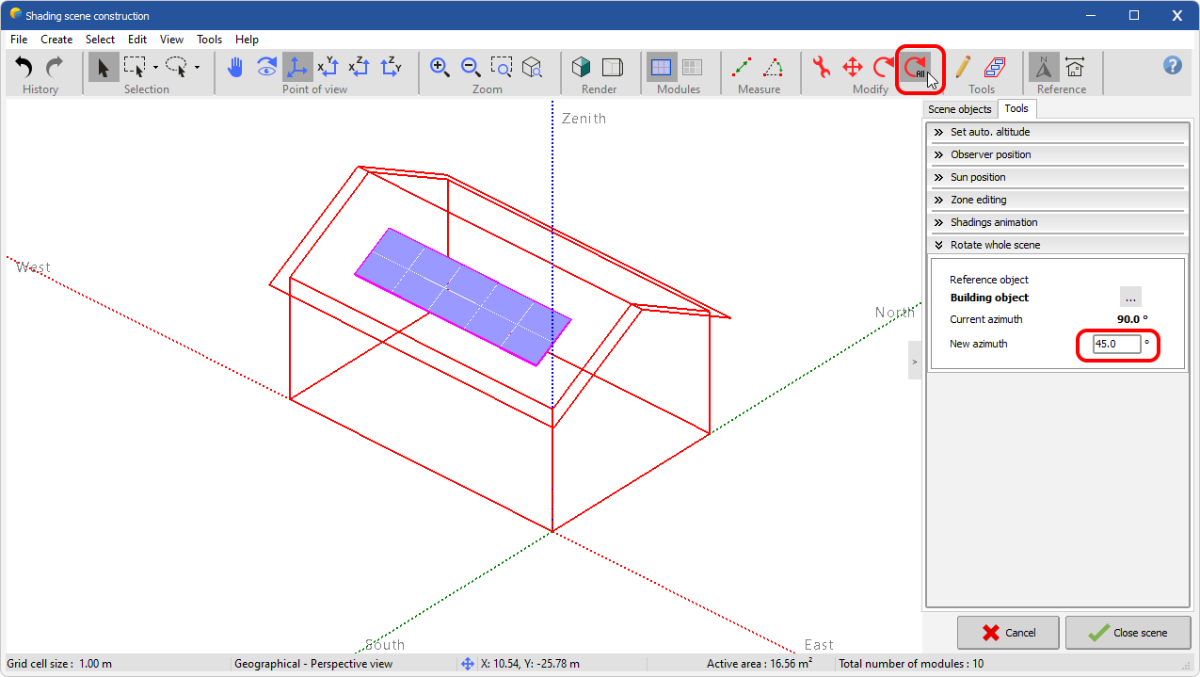
To solve your problem, you can simply select the whole scene and rotate it 180° with the rotation tool:
-
Hi JLS,
The best way is to use the "Rotate whole scene" tool:
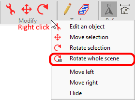
If the button doesn't appear, you'll have to right click on the ribbon in the 'Modify' part and select "Rotate whole scene". This will add the button:
-
FYI, I fixed the bug ? with double click, it will be available in the next patch (7.3.2). Thank you for bringing it to us ?
-
You can also import objects from Sketchup in DAE or 3DS format, by default all imported objects are considered as obstacles, and will generate shadows.
-
Hi @dtarin, you're not the first to report this problem, but I couldn't reproduce it on my end because I didn't go through the double click. Now that I have the correct mode of reproduction (with the double-click) I will be able to fix it for next version.
In the meantime, go through the right-click->Add fields, it works this way
-
The import formats supported by PVsyst are PVC, DAE, 3DS (https://www.pvsyst.com/help/index.html?sketchup.htm) and H2P (https://www.pvsyst.com/help/index.html?helios_3d.htm).
-
This error is caused because orientations 2 and 3 are very close.
To solve your problem, you must decrease the detection threshold in the advanced parameters (Parameter #703), for example 0.1° instead of 0.5°:


Digital model
in Simulations
Posted
Hi Meurville,
The IFC format is not supported by PVsyst. As mentioned, only 3DS, DAE, H2P and PVC are supported.
The solution is to convert your IFC files into one of the supported formats (DAE or 3DS) with a dedicated tool such as Sketchup.
Regards,
Stéphane M.