


Lazare Fesnien
-
Posts
269 -
Joined
-
Last visited
Posts posted by Lazare Fesnien
-
-
Dear Emi,
You can simulate virtually your entire project.
Attention it is not possible in PVsyst to mix two orientations with different lengths of strings.
I just made your system under PVsyst, you just need to make a little change in the naming of the orientations in order to simulate your system correctly.
-
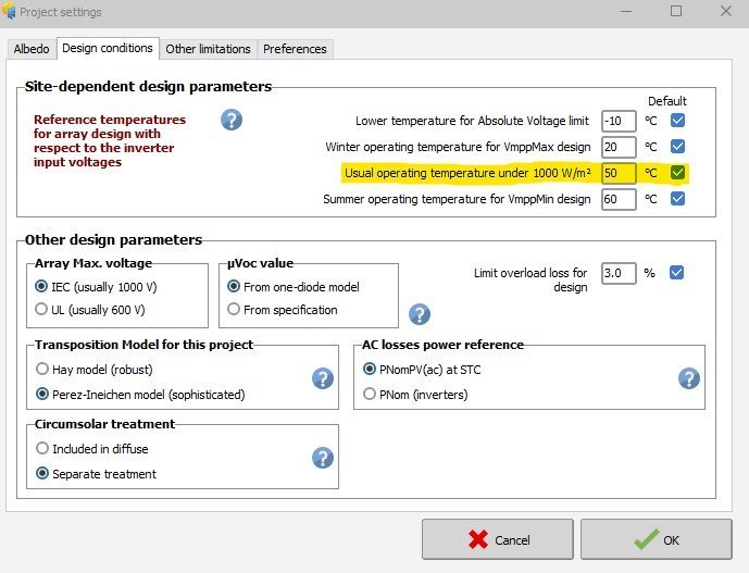
Dear Gba,
This is a project setting.
By default the value is 50°C, you can modify it from "Project settings" :

-
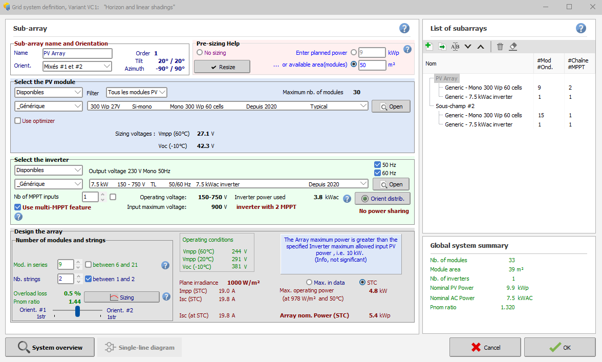
Dear Emi,
In your configuration you must define orientation1 and 2 with "mix 1 and 2" the define your sub-array N°3 as orientation N°3.
This will allow you to position three orientation on two MPPTs like the example below :
-
You must use the "power sharing" tool to set the power distribution correctly
-
Dear Emi,
You set one string for two MPPT inputs, it can't work
-
Dear Ynesse,
VmppNom: Nominal MPP voltage is sometimes specified by the manufacturer.
In this case this may be an indication for the optimal number of modules in series.
Weakly used in the sizing tool in the present time
-
Dear Meurville,
To limit the inverter, you must click on "energy management" then "Grid injection limitation"
Regards
-
In some months
-
Dear Paaul,
No, at the moment you cannot set multiple orientations in a standalone system.
This feature will be developed later -
Dear Manos Dro,
To do this, you must create sub-array and then check the multi-MPPT box at the line level of the inverter.
Then, the "power sharing" option is unlocked and allows you to distribute your power correctly"
Regards
-
Dear Furkann71,
Please send your questions to support@pvsyst.com.
You ask a lot of different questions in the same subject, it's not how this forum works
-
Our languages of communication are French or English.
Please translate your message
-
Dear Fofone,
Theoretically yes, after it will be privileged the multiplication of cable like 3 x 3G500
-
Dear Fofone,
Yes PVsyst allows you to do this, you can look in the Commercial and Utility demos available from PVsyst. -
The ohmic losses behave in a quadratic way with the array current: Ploss = Rw · Iarray².
Now if the array is not operating at STC, the wiring loss fraction will become:
Ploss / Parray = Rw * Iarray² / (Varray * Iarray) = Rw * Iarray / Varray.
i.e. proportional to Iarray. This means that at half the irradiance (half the current), the wiring loss fraction will be half, etc. Therefore the Wiring energy loss has to be evaluated at each hour of the simulation, and accumulated in terms of energy.
The final result of the Ohmic wiring loss (in terms of percentage) as shown on the loss diagram will be from this hourly energy balance. It is usually of the order of 60% of the Loss fraction specified a STC.
-
Dear Detroit Solar,
Thank you very much for your interest in a PVsyst training.
We propose some online personalized sessions in the form of Consulting and PVsyst project support, to answer specific requests (no standard sessions for the moment).
If you are interested in this service, you are kindly requested to request an online quote here: https://www.pvsyst.com/consulting/
We will establish a program relevant to your specific requirements.
Our sessions last for 2 hours (including participants question time) and are charged CHF 700.-
Our online sessions are limited to 5 participants per session.
We do not provide any guarantee relating to your simulation results.
In the meantime, we have designed several online video tutorials which we invite you to watch:
https://www.youtube.com/channel/UCMzsEWHk3f7XD_dg1lngmzg or access our online course at: https://vimeo.com/pvsyst
If you have a technical question, please feel free to send an email to support@pvsyst.com
-
Dear Wanderson Alves,
Our discussion languages are French and English, please translate your email.
Regards,
-
The IAM model is defined with the PV module parameters, page "Additional data > Customized IAM".
Here you should define the glass surface type, and PVsyst will attribute the corresponding IAM model.
The PAN file of low light measurements, apart from the integration of this data, is extremely sensitive.
The reference is that at 200 W/m2, the real efficiency is -3%.
-
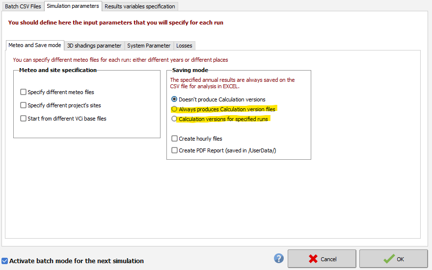
Dear Daniel,
In the batch mode you can do this :

-
Dear Joao,
Please, try to enable the anti-aliasing rendering option:
-
We are pleased to announce that our collaborators #BrunoWittmer, #MicheleOliosi and #AgnesBridel will be present at the 40th European Photovoltaic Solar Energy Conference which will take place in Lisbon (Portugal) from September 18 to 22, 2023.
For more information : https://www.eupvsec.org/index.phpWe look forward to seeing you there
-
Dear Andel,
Usually we can estimate that 1 ha corresponds to 1 MWp of PV module.
-
Dear Sana,
To do this, you must create sub-array in the list on the right in the "system" window.
Please read our FAQ : https://www.pvsyst.com/help/sub_arrays.htm?zoom_highlightsub=sub+array
-
Dear HTC,
Our communication languages are French and English, please communicate with these languages.
To answer your question, here is our FAQ concerning the single-diode model:
https://www.pvsyst.com/help/pvmodule_model.htm?zoom_highlightsub=one+diode+model
Regards

AC Losses in tranformer
in Problems / Bugs
Posted
Dear Shashank Sharma,
These losses appear in the following loss diagram: