All Activity
- Today
-
 CarlosN joined the community
 -
 bicakmodelleri joined the community
 -

Snapping objects issue (cable) - PVsyst 8
David Bourdon replied to David Bourdon's topic in Problems / Bugs
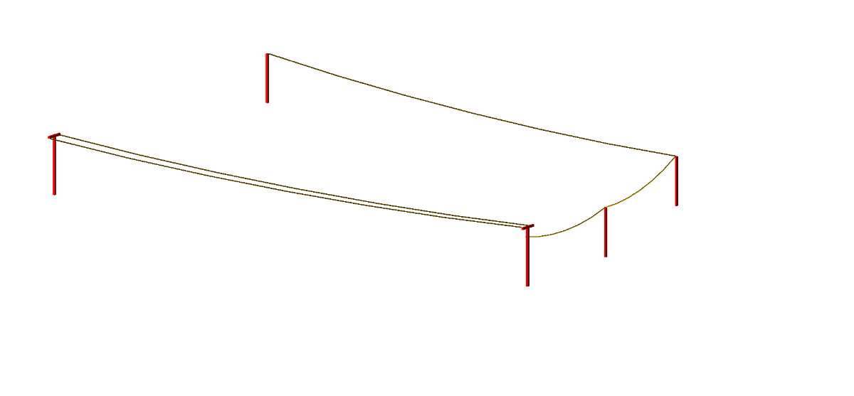
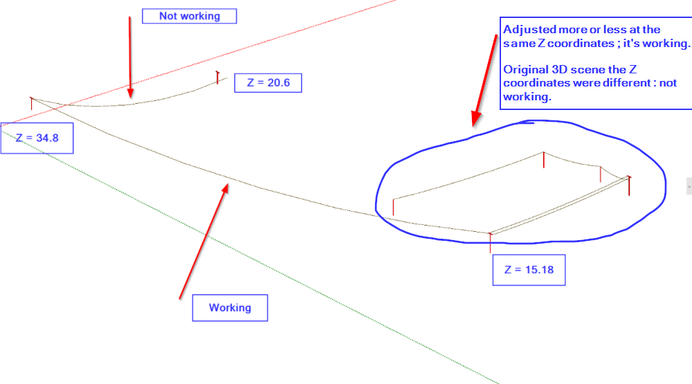
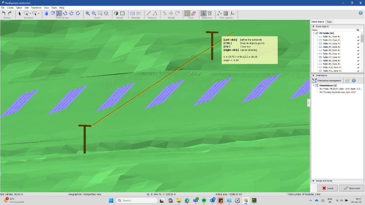
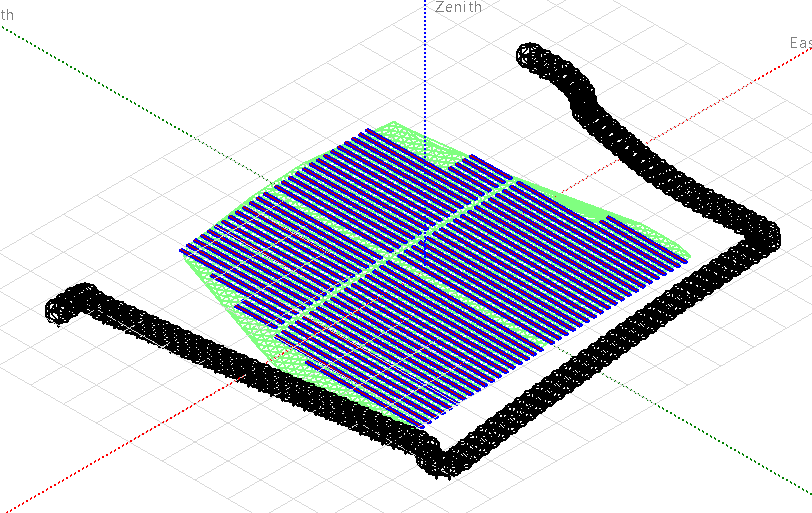
After trying several potential options to solve this I may have found a possible explanation (but not 100%). I've saved my poles as shading selected objects and started a fresh new simulation with a random meteorological file to avoid any external effect of my 3D : no effect, still not snapping. I've opened the shading selected objects in PVsyst 7.4.8 and again started a fresh new simulation : no effect, still not snapping. Then I've noticed that the snapping was working for several poles at the same altitude so I've tried changing the altitude of my other poles and then it worked with no issue. It means that depending of the altitude (I don't know what the tolerance is), the snapping function is not able to find the edge to connect the end of the cable object. 1st picture, they are more or less at the same Z coordinates ; snapping is working perfectly 2nd picture, the poles are at a different altitude, not snapping, mainly X coordinates which is affected by the poles location Now what I can't explain is that the snapping is working for another pole at a different altitude, mainly with a Y coordinates affected by the poles location... I can share a *.SHO file with my poles position and cables snapping/not snapping to help identify the issue, if necessary. Thanks for your feedback, D
-
The cable type or installation mode may affect the resistance only in terms of "Resistivity as function of the Temperature". In PVsyst, the resistivity is specified for a temperature of 50°C (alu or copper). This will be modifiable in a next version of PVsyst (probably in V 8.1). But in practice, we usually don't have any information about the cables temperature in the system during operation. NB: The resistivity variation is 0.39 %/°C. Applied to a loss which is usually of the order of 1% of the total energy, the effect is completely negligible in the simulation results.
-
Thank you for the detailed explanation regarding AC losses and the reference power selection. It's very helpful to understand how these choices impact ohmic losses. Could you please elaborate on how different cable types might affect the overall resistance and thus the ohmic losses in the system?
-
 shuwan joined the community
 -
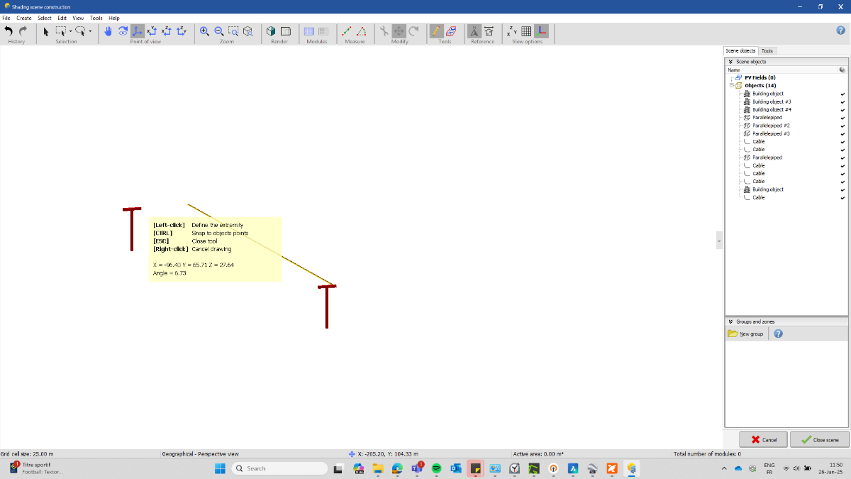
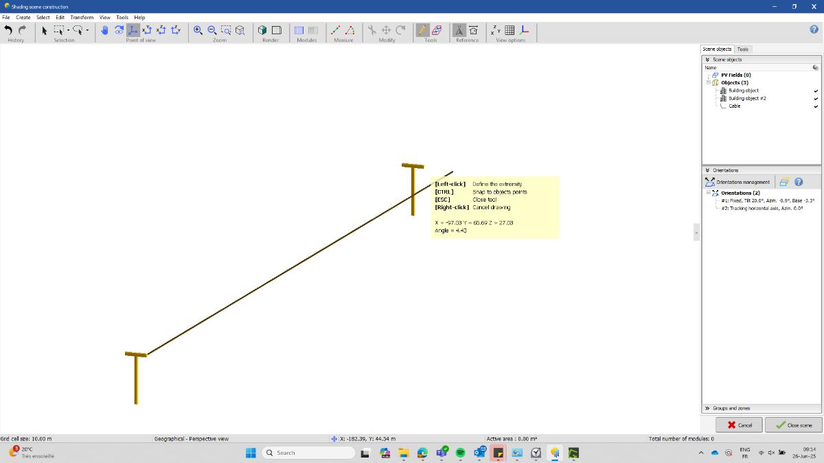
Good Morning PVsyst support and PVsyst community, I'm creating this thread as I've been struggling for several hours now trying to draw an overhead line in my 3D scene and use the snapping function (by pressing CTRL) of the cable object to connect both ends of the cable (I use PVsyst for years now, so it's not new to me and I've done it several times in the past without any issue). For some reasons, the cable object is not able to recognize the edge of my second shading object to connect. I've tried several type of shading objects to see if it makes a difference but so far still not working (parallelepiped, composed object from parallelepiped, electric pylon) The start point is never a problem but the end point is never found and can't connect to my second shading object. I've tried to remove the other objects from my 3D scene such as topography, ground image, even the modules and keeping only the two "pylones" that I want to connect but it's not changing anything. I'm using PVsyst 8.0.13 and tried as well with 8.0.12, but same effect. If I place my cursor where I want to connect the end of the cursor and then press CTRL, the end point moves to another location with nothing visible. I've tried to manually place the cable between the poles but moving in 3D it's almost impossible to do something clean. If I start a fresh new 3D scene for the same project and try to create basic parallelepiped and connect the cables it works... If you have any idea or advise to solve this... Thanks in advance ! Best regards
-
 Ianbel488 joined the community
 - Yesterday
-
 Greetings PVsyst team. I'm working with a PV system with bifacial and monofacial modules. I've already created differents orientations for each sub-array, but now I wonder how PVsyst consideres theses two kind of modules on simulation. There is any other parameter I should keep my eye on it? In future versions, would be possible to set degradations per sub-array?
 -
 Danwen49 joined the community
 - Last week
-
The number of rows is only used for the bifacial calculation for the backside irradiance, where the simplified 2D cross section view is needed. For the front side, the electrical shading is fully simulated as defined in the 3D scene.
-
That makes sense, but if partitions are defined to account for the electrical effect, wouldn't this approach ignore edge effects and the N-S space between tracker tables?
-
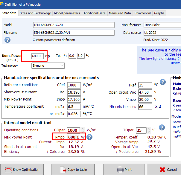
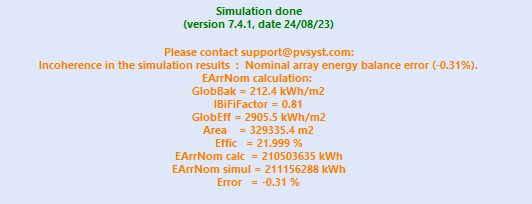
This warning has nothing to do with the Pmpp difference between the nameplate and the one-diode model result. This is due to a problem in the simulation process (irradiance calculations), which has been corrected in the V 8.0. But sorry, I can't say anything more without analysing your project in detail.
-
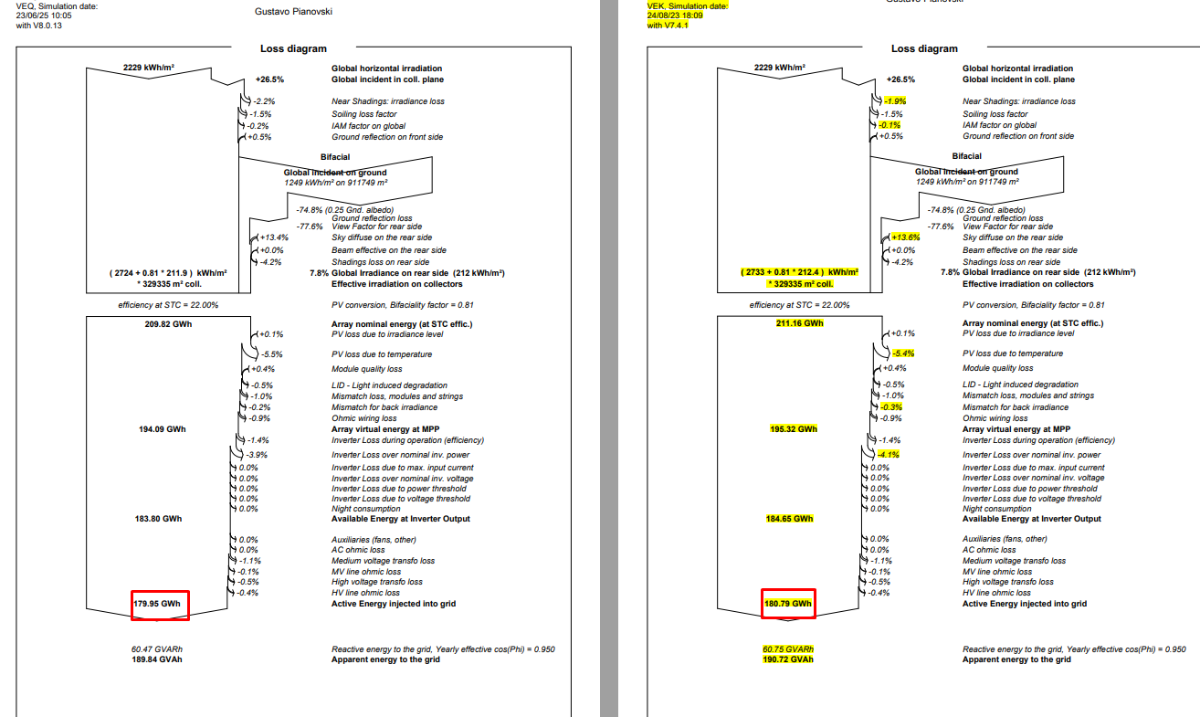
Dear Michele, I am working on a V7.4.1 project to extract the some variable, and the following warning appears: I analyzed the .PAN and the difference observed is 0.01%. However, the difference in E_Grid is 0.46%, of which 0.3% is due to Near Shadings losses: In the simulation using Version 8.0.13, this problem does not appear. Does simply performing a new simulation in Version 8.0.13 solve this problem? What are the reasons for this warning? What updates have been implemented to fix this bug?
-
The number of rows refers to the number of rows in the 2D cross-sectional representation of the system, assuming "unlimited long tables", and is relevant for the calculation of the effect of the first and last row of the array. In your case it would rather correspond to 38 rows, imagining the view in 2D. Number of sheds (rows) and accuracy - PVsyst documentation
-
 Kelsey Lou joined the community
 -
PVsyst is a worldwide distributed software. We obviously cannot include such national or local requirements, especially like this one which seems to be very evolutive. Moreover, we don’t want to take any responsibilities regarding such national administrative rules.
-
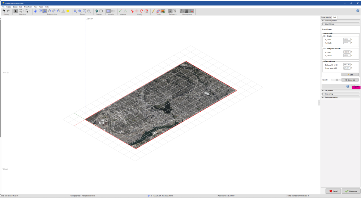
 Dear Shivam The map size is limited, but if you want to import an image, you can do the following: Take a screenshot of a satellite image. Then import it via File > Import > Import a ground image. Finally, you need to scale the image to match the actual scale. To crop an imported image: Double-click on the image. You will see "Ground Image" with a Crop option (highlighted at the bottom right). Click on it to crop and resize the image. Regards,
-
 Bhumika joined the community
 -
 Mangesh Punekar joined the community
 -
 How to import specific location imagery and terrain data if the weather station coordinate is different from the actual location. The location is outside the map limit in the Pvsyst interactive map. Also, can we crop the image or terrain map after importing it into the 3D scene?
 -
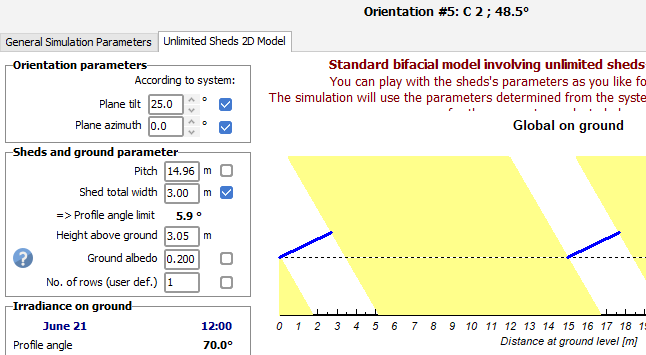
The below shade scene contains 72 tracker sheds total, but 38 rows of trackers E-W. Should I define the number of sheds in the bifacial system definition as 72 or 38? And why is one method better than the other?
-
I am working on a PV system project that requires BABA-compliant PV modules, inverters, and BESS to be specified: Build America, Buy America (BABA)-Compliant Solar Manufactured Products | Department of Energy Can you create an option in PVsyst to display only BABA-compliant solar products? Alternatively, can PVsyst developers monitor this list and add the BABA-compliant solar products to the PVsyst database?
-

Bifacial model not working for single tables in PVsyst 8
Miguel G replied to Miguel G's topic in Simulations
Thanks for your assistance, Michele. -

Bifacial model not working for single tables in PVsyst 8
Michele Oliosi replied to Miguel G's topic in Simulations
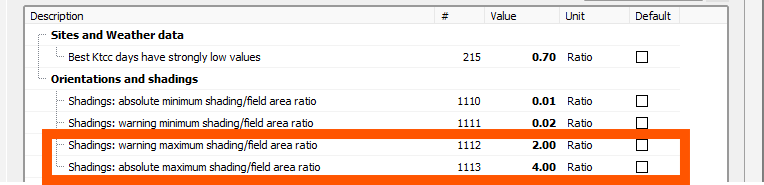
Hi, It was indeed possible to define situations with only a single row + 3D scene + bifacial model in previous patches. However, this was not the intended behavior and was a possibility that was exposed by a bug. We would not be able to guarantee that the calculations were properly handled in this situation. We have recently corrected some issues in terms of number of rows, and that has had the effect that the above unwanted exposure was corrected as well. Currently, the calculation with a single row in an orientation (such as your orientations 2, 3, 4, and 5) can only natively be realized with an unlimited orientation. There are therefore two workarounds: Model orientations 2-5 as unlimited orientations with one row. Duplicate the 3D tables from orientations 2-5 and any objects that may shade them. The duplicates should be placed far enough on the scene so that there are no unwanted interactions. In this way, PVsyst recognizes two rows instead of one. Since they are sufficiently spaced, mutual shading effects are negligible. You may need to alter the following advanced parameters (Home window > Settings > Edit advanced parameters) to avoid some problems with a larger scene than the modules defined in the system window This solution does not work with Module Layout definitions (because these necessitate a perfect match between 3D scene and system) Please note that supporting 1 row bifacial orientations is in our internal roadmap, and I will rebound on your request with discsssions to see whether we can anticipate this feature a little.
-
Hello, In general it is fully possible to continue a project made in 7.4 in version 8.0.
-
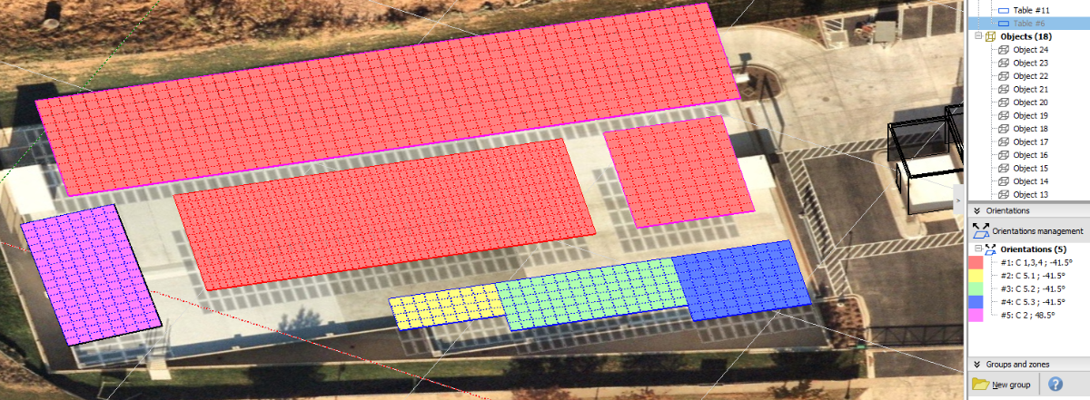
Hello, When PVsyst 8 was released I was able to run a complex carport PV simulation using the bifacial model (see attached report). It consists of 2 orientations but actually I defined 5 orientations because although the southern carports share the same orientations, their table widths are different. I took advantage of the new bifacial model features of PVsyst 8 in regards to the pitch and number of rows defined by the user for the cases when you don't have an unlimited-sheds type of array. However, now with 8.0.13 version when I try to run again the simulation (because I need to get an 8760 file), I'm not able to run the simulation with the bifacial model anymore. I got the following errors for all orientations except for orientation #1. I don't understand why I'm getting this pushback, when we haven't modified anything to the original PRJ. In fact, when I try to modify the bifacial model values (such as tilt, pitch, width, and so on) for those orientations, PVsyst doesn't save that information and applies a generic 25° tilt a 0° azimuth, when in reality all arrays have a 5° tilt in System and 3D definitions. See an example for orientation #2 (-41.5° azimuth). I would really appreciate any advice on this issue. Thanks! MoCo 6th District Police Station V6.VC0-Report.pdf
-
Good morning Michele Thank you for your valuable advice. I wanted to know if the time series data on snow depth can be reflected in the albedo, so I understand now. For the warning on the clearness data, I will email the files you pointed out to support@pvsyst.com. I will probably send it to you within 24 hours, so thank you.
-
I just upgraded PVsyst from version 7.4 to 8.0. Can I open the PVsyst files created in version 7.4 with PVsyst version 8.0 or do I need to start from scratch?
- Earlier
-
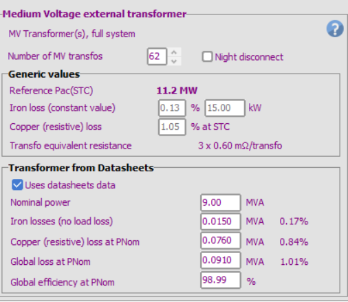
The transfo loss reported by the simulation (loss diagram) is the sum of the Copper losses and the Iron losses. Remember that the Iron losses are a fixed value, permanent (24/24) if you did not check "Night disconnect". It represents an important contribuition.
-
Indeed, the hours where the wind exceeds the given threshold, the simulation will be done with the trackers in the defined wind stow position. You will not directly see any losses in the diagram though indeed it will result in a less optimized Global Incidence Irradiation. To properly evaluate the impact from the wind stow, you would have to run one simulation without activating this functionality and compare the two simulations.
-
Hello, I recently found that the MV transfo loss in the loss diagram is somehow larger than the value I defined in the ohmic losses section, for example in the datasheets data, I defined the global loss at PNom to be 1.01%, but the MV loss in the loss diagram shows 1.4%. Since the Operating power of MV transfo is sometimes lower than PNom, MV transfo loss should be lower than 1.01%? Do you have any idea about this? Thank you!
-
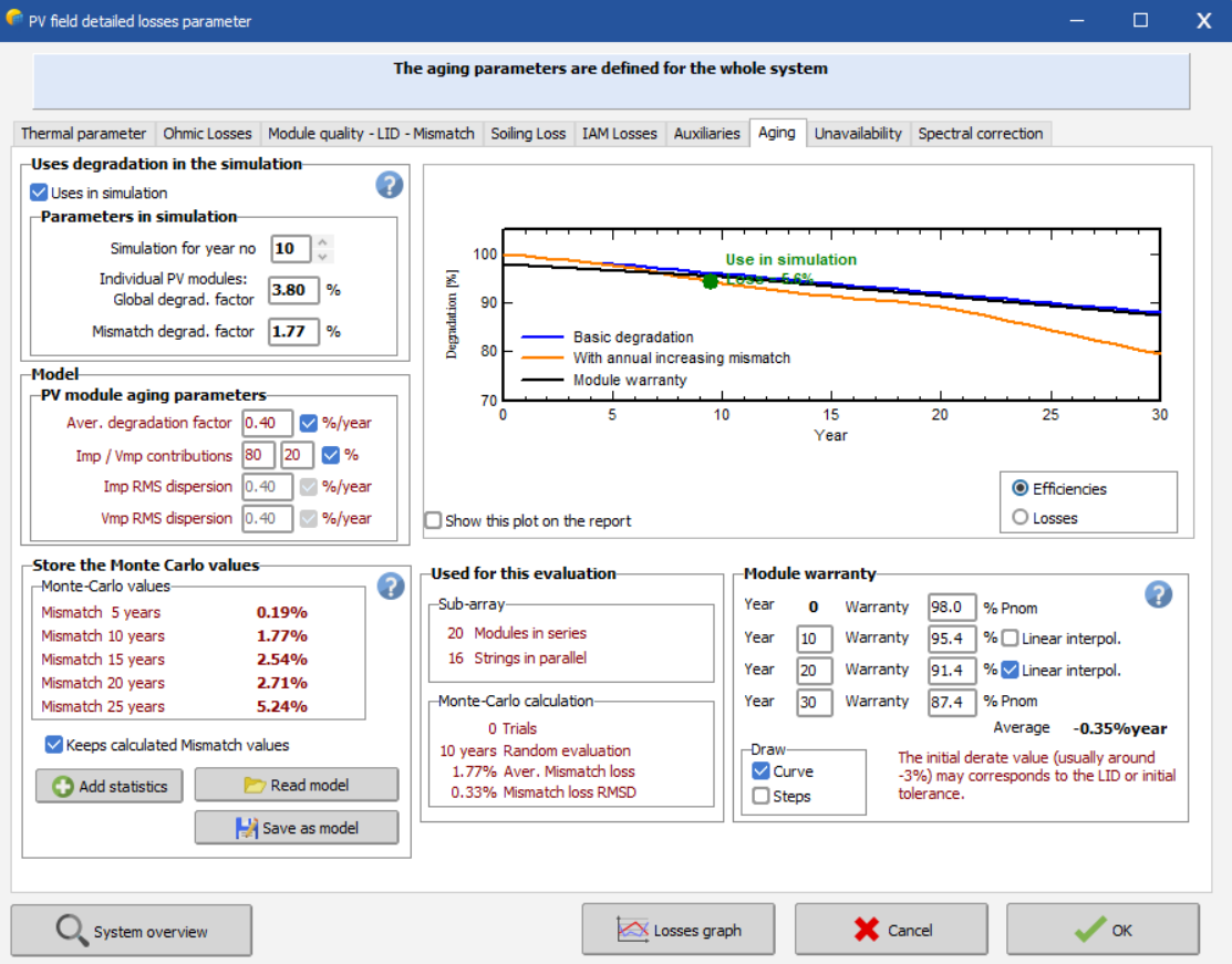
Good morning everyone, I would like to ask how can we determine the average degradation value and the Imp/Vmp RMS dispersion of the pv panel? I am using LongI LR8-66HGD 620Wp model. All reference are welcomed. Thank you for your time.