All Activity
- Past hour
-
 Dear ShivamPandey, Please email us your PVsyst LOG files (using menu <File> <Export logs>) at: support@pvsyst.com so we can analyze what happened and try to reproduce the issue you reported. Best regards.
 -
 Mxolisi joined the community
 - Today
-
Dear ShivamPandey, Please email us your PVsyst LOG files (using menu <File> <Export logs>) at: support@pvsyst.com so we can analyze what happened and try to reproduce the issue you reported. Best regards.
-
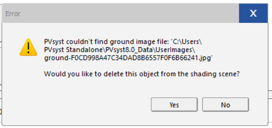
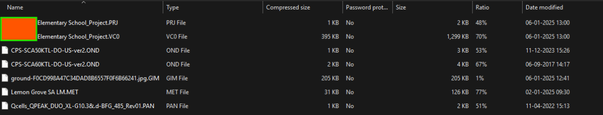
 Hi I have an older Pvsyst project export zip file, but when importing it into PVsyst, it is showing the following errors. Older project is created witjh PVsyst 8.0.5 Zip Folder contains all the files exported. Same is the issues with the background image imported from map service within the near shading. Map is not showing up when imported into a different machine or PVsyst
-
PVsyst Having the same issues, any solution for this
- Yesterday
-
 Nitish Singh joined the community
 -
 zmmzmzsha joined the community
 - Last week
-
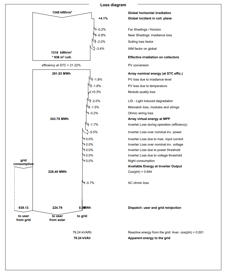
All the most important losses are illustrated in the loss diagram that is generated after running the simulation. Here you can clearly see what kind of losses your project suffer from. The P90 will depend on the variability and uncertainties you define in the Energy management window.
-
 Kafin06 joined the community
 -
Dear Andres, Unfortunately, this is a bug with PVsyst version 8.0.16 and we will fix it in future releases. The bug also affects importing "meteonorm software (*.hor)" data. In the meantime, several workarounds are possible: Import horizon data from meteonorm API ("horizon from web sources") Copying your .hor file in the PVsyst8.0_Data/Shadings folder and importing it with the "PVsyst internal file" option If neither options above work for your situation, reverting back to PVsyst 8.0.15 https://www.pvsyst.com/old-versions/ I hope this solves your issue
-
 ClaytonWocky joined the community
 -
 Wascame joined the community
 -
What are the factors that affect a high specific production and P90 value? I am working on multiple simulations and there is one simulation that always has a high yield (kWh/kWp/day) and I can't figure out why.
-
PVGIS horizon imports are currently not working properly as they are only importing 180deg of the horizon from 0deg to 180deg and not including -180deg to 0deg. This is a problem with both 5.2 and 5.3 currently.
-
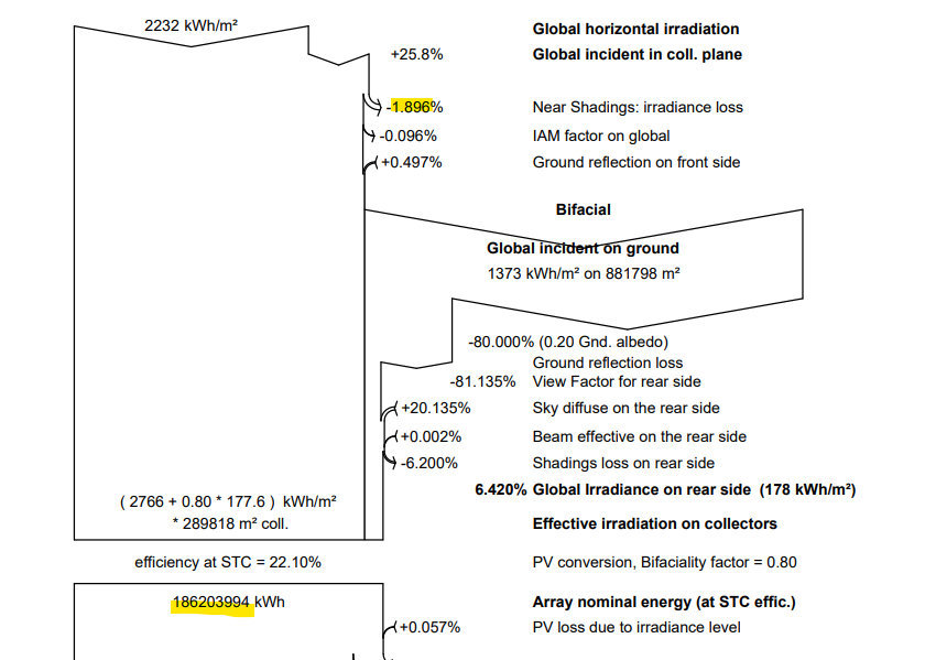
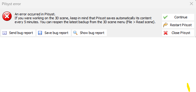
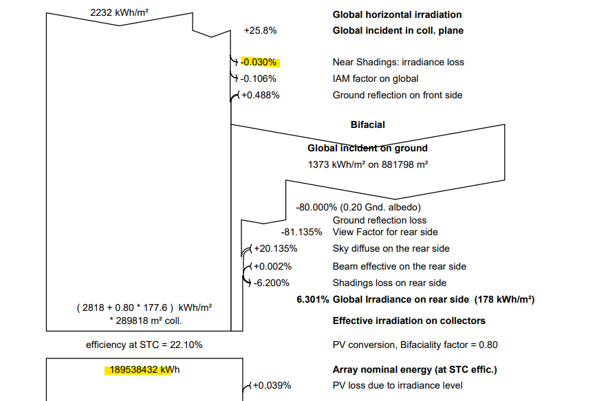
Greetings all. The recently released version 8.0.16 introduced the feature of including object shading in the calculation of diffuse shading in 3D model. However, I noticed that when using this feature, the values for near shading losses do not match the values when using the ‘all trackers’ feature. All trackers: Custom tracker with object shading included: In addition, using the “object shading” feature causes the software to crash.
-
 Birhan Mezgbo joined the community
 -
 elie khourieh joined the community
 -

Inverter Clipping (overload loss) for On-grid
Muhammed Sarikaya replied to Ziad's topic in Simulations
Dear Ziad, Without the project, I can’t know what the issue is. Could you please send us your project at support@pvsyst.com and explain what the issue is? Regards, Muhammed Sarikaya -
 vasisa joined the community
 - Earlier
-
Hello, There is something I can't fully understand , Shouldn't there be a limit for energy generation (Euseful) as Pnom ratio (DC/AC) is increased then Euseful should decrease again because of the overload losses? because I noticed that generation keeps increasing as i continue to add more strings for the same inverter till reached the max number of strings allowed. Thanks.
-
 Ziad joined the community
 -

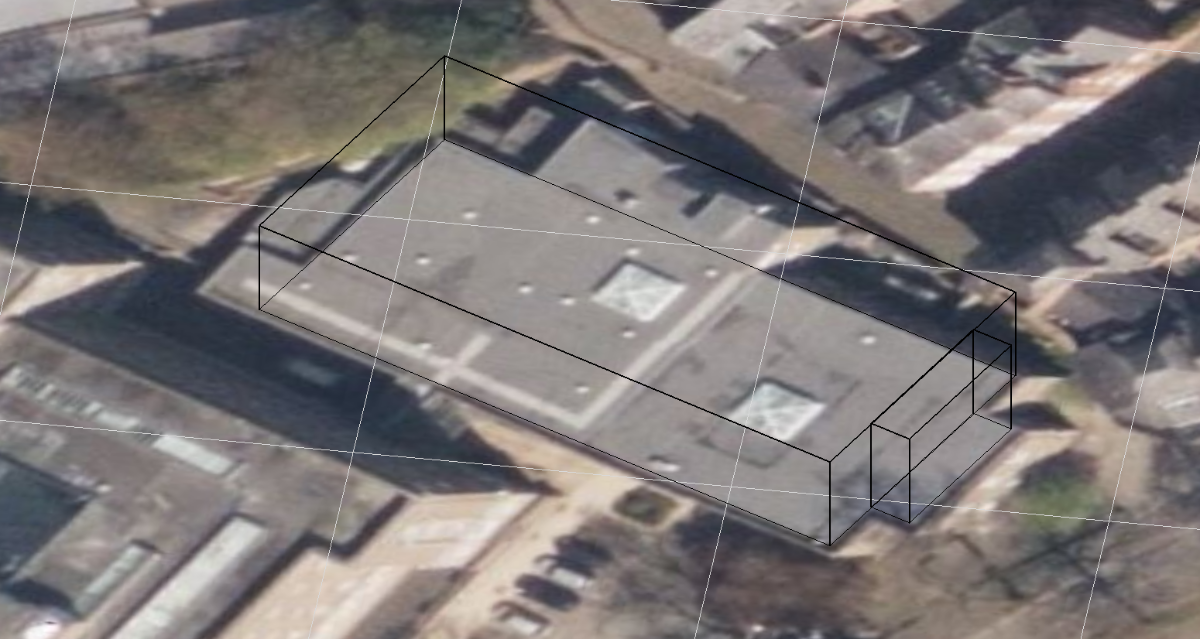
How to Build a Parapet around a Building in Near shadings?
Jéremie Bernier replied to MayersSolar's topic in How-to
Hello, there is no dedicated building element for such a parapet. However you can use elementary shading object like parallelepiped all around the roof edge. -
Hi Hizir, Thank you for your reply. I see the Regular and Bold for Airal Unicode MS fonts in the C:Windows>Fonts folder. Fortunately, my company installed an update for PVsyst this morning and now I can view and print reports again. Hopefully it will stay this way! Thanks again, Ben
-
Hi there, I’m struggling to model a parapet around my Near Shadings building in PVsyst. The parapet is 0.3 m wide and runs along the roof edges. Is there a recommended way to create this? I tried adding a 0.3 m-high wall around the building edges, but that feels a bit rudimentary. Is there a more efficient tool or feature for this? Thanks in advance!
-
 The structure shading factor is design to reflect the area covered by the structures. The electrical effect of this shading should be reflected in the mismatch loss factor. Thus if I understand your example correctly, the mismatch loss factor should be set to 40% if 40% of a cell in the concerned sting is shaded. For the structure shading factor, define only the ratio of the area covered by structures to the photovoltaic area.
 -
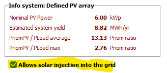
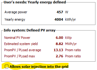
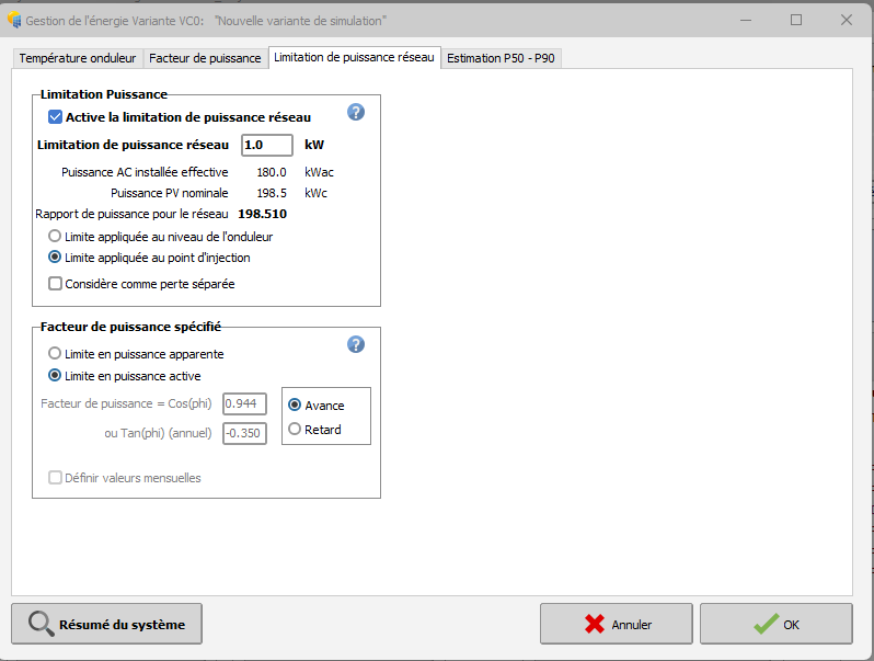
This is quite normal as you have defined a grid limitation of 1 kW (for a system of 200 kWp, 180 kWac). You can notice that the apparent value is 79 kVah, to be compared to a global delivery to the user of 224 MWh, i.e. 0.04%. Please note that you have the opportunity of completely forbid the injection to the grid when you define the self-consumption:
-
Understood - thanks for your response!
-
Dear Ben Arial Unicode Bold and Arial Unicode Normal font seem to be missing from your computer. Could you please check that you have it installed in your C:Windows>Fonts folder (Normal and Bold should appear for Arial Unicode MS) : If not you can install it from here: https://freefontsdownload.net/free-arial-unicode-ms-font-36926.htm If the problem remains, please export and send your log files to support@pvsyst.com by using menu "File>Export logs" Kind regards,
-
Following a recent update, I'm no longer able to produce a complete report in PVsyst. As you can see in the attachment, the pages are missing most information. Please let me know what I should do to restore the report functionality.
-
 Hi Linda, Thank you for your reply! Can you also please clarify what your estimate is for structure shading factor based on my post (10% or 40%)? And isn't your comment on mismatch effect related instead to structure shading factor. i.e. where you wrote, "as the current in a string is the current in the worst cell, if the structure covers x% of one cell, the shading effect will be x% for the concerned string. For example, the loss may be reduced by a factor of 2 if the structure covers half a cell (or two half cells)." Thanks again, Ben
 -
I would like to model a PV system with dynamic clamping (i.e. no electricity reinjected into the grid). The building’s consumption data has been uploaded in the “self-consumption” section. In the “energy management” sections, the grid limitation has been set to 1 kW with the option “limit at the injection point” (since setting the limit to 0 kW did not trigger any clamping). In the loss diagram, the active energy injected into the grid is correctly shown as 0 MWh. However, the apparent energy injected is not equal to zero. How can this be explained? Thank you in advance.
-

Battery being under-utilized in self-consumption simulation
André Mermoud replied to Dean O's topic in Problems / Bugs
Yes indeed, the battery model of PVsyst uses information which is not always present on the datasheets. Some datasheets are really very brief. When you have to define a battery by yourself, you are advised to start from an existing battery, and adjust the relevant variables (mainly technology, kind of battery, number of cells in series and parallel, internal resistance (check dafault), self-discharge (check default), lifetime (numbe of cycles), sizes and weight -

Report shows spectral correction applied even when it isn't
Chen replied to LauraH's topic in Problems / Bugs
OK, thanks -
Yes, you can create elementary shading objects in your scene, whether you imported the scene from a 3D file or created it yourself
-
Report shows spectral correction applied even when it isn't
Linda Thoren replied to LauraH's topic in Problems / Bugs
it is the coefficient set for that specific PV module technology. You can find additional information in the following help: https://www.pvsyst.com/help/physical-models-used/pv-module-standard-one-diode-model/firstsolar-spectral-correction.html#spectral-correction-in-pvsyst


.png.8858780cf01ee36b4ce12fc3eb22fa30.png)