All Activity
- Past hour
-
Modifying the OND file is another way
- Today
-

Limitation of pan file for BC and HJT module
Luca Antognini replied to Chen's topic in Problems / Bugs
Dear Chen, We are currently investigating how to adapt our model to such technologies. It will take some times, as we want our modification to be backed-up by high quality experimental data and be applicable to the whole of our PV module database. We will present an update of our research at the upcoming EU-PVSEC. -

Iso-Shading Diagram when no shading object is present
Robin Vincent replied to PVsystUser's topic in Shadings and tracking
I guess, based on your scene the trees are not the major contributors to the shadings. It could be that all your rows don't have the same height, which is not taken into account in the backtracking algorithm. It could also be a bug. At the very least you should try it with the latest PVsyst version to see if you get your expected outcome or is the shadings are still looking similar. But again for this kind of questions you should contact PVsyst support instead of using the forum. There is only so much we can say based on a few screenshots. - Yesterday
-
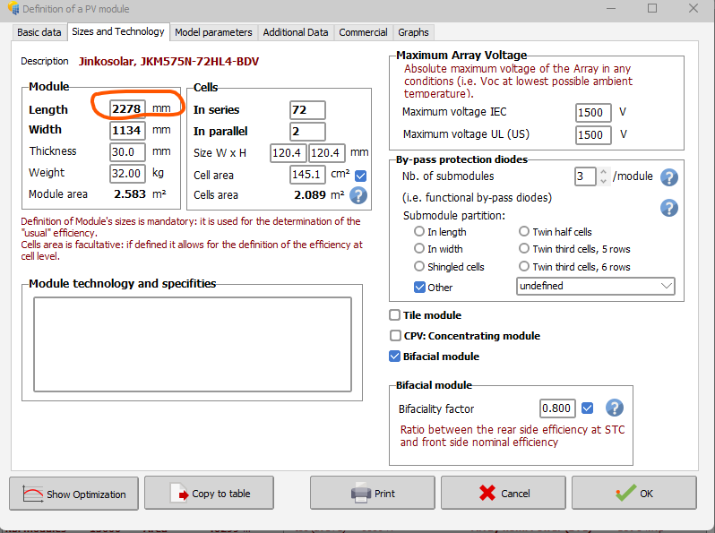
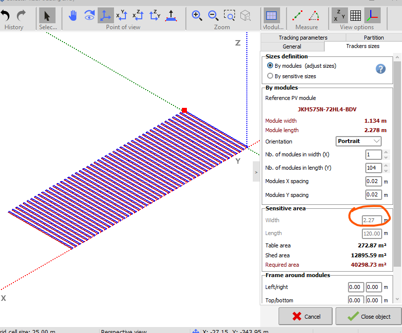
under system, i have selected a module which has a length of 2278mm in the pan file. under shadow scene, when i select size definition: by module, it shows width of sensitive area of 2.27m. What is the solution?

-

No import of meteo data, after selected and confirmed location
JMC replied to Toni's topic in Meteo data
I have the same issue. Using PVsyst 8.0.9 And I have been lead to believe I've got full admin privileges for this machine. (I can download and install this software.) -
JMC joined the community
-

Iso-Shading Diagram when no shading object is present
PVsystUser replied to PVsystUser's topic in Shadings and tracking
I haven't chosen a good word. Instead of "similar" I should have said why there are still shading when there is no tree. From your answer I realized that's might be the effect of backtracking. Although I am surprised because backtracking is activated in both runs and I have checked it few times. Could it be a glitch? -
 Anton113 joined the community
 -
 Sorry, I'm not sure why this is happening on your end—we haven't encountered the same issue. You might try maximizing the window to see if that helps?
 -
Hello Marija, Indeed, the only possibility is to apply a grid limit for the full system. As you suggest, a workaround would be to create a variant for each sub-system and aggregate the results. I will note your use-case for possible future development of for instance having the possibility to define the limitation per sub-array (as for the ohmic losses for instance). Thank you reaching out
-
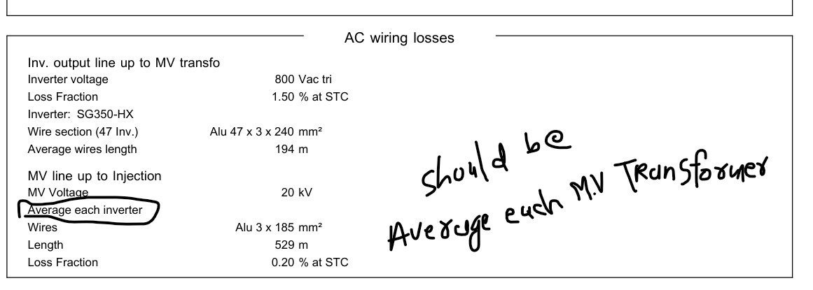
 Dear PVsyst Team, I have been reviewing the AC wiring losses in the system, specifically the data provided in the report for the Inverter output line up to the MV transformer and the MV line up to the injection point at 20 kV. Upon reviewing the report, I noticed a potential misunderstanding regarding the interpretation of the "average wire length" in the MV line section. In the report, it mentions: Average wire length for the MV line up to the injection point as 760 meters. However, the way the data is presented could lead to confusion. Initially, it seems that this distance refers to the wiring between the inverters and the MV transformer. But upon further consideration, it seems that the 760 meters should be the distance from the MV transformer to the injection point (where the power is fed into the grid at 20 kV), not per inverter. To clarify: The average wire length should indeed be for the MV line from the transformer to the injection point at 20 kV, and not per individual inverter. The inverter-to-MV transformer wiring and the MV line from the transformer to the injection point are distinct, and it's important to apply the loss fraction of 0.25% to the wiring between the MV transformer and the injection point, where the power is being injected into the grid. Could you please confirm whether this interpretation aligns with how the data is calculated in PVsyst? And, if possible, could you confirm the accuracy of the wiring loss fraction applied to this MV section? Please have a look to the attached screenshot of the PVsyst report. Looking forward to your insights and confirmation. Best regards, NIken
-
Hello, I'm working on a PV project that is divided into 9 zones, each with its own grid export limit of 4.44 MW AC. Overpaneling is allowed, so the DC side can exceed this limit. In total, the full plant would have 40 MW AC and potentially more on the DC side. I know PVsyst allows setting a Grid Power Injection Limit at the system level, but I haven't found a way to apply individual grid export limits per zone within a single simulation. Is there a way to simulate per-zone injection limits in one project? Or is it necessary to simulate each zone separately and then aggregate the results? Thanks in advance for your help!
-
Iso-Shading Diagram when no shading object is present
Robin Vincent replied to PVsystUser's topic in Shadings and tracking
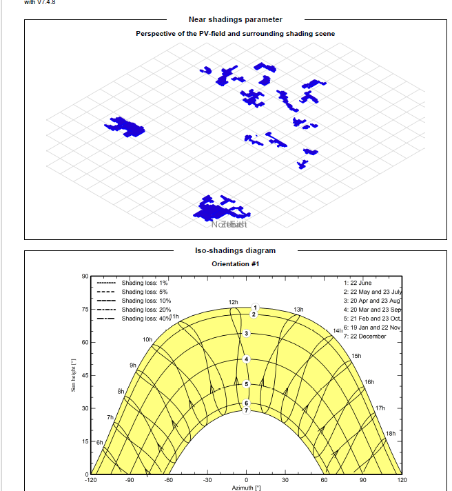
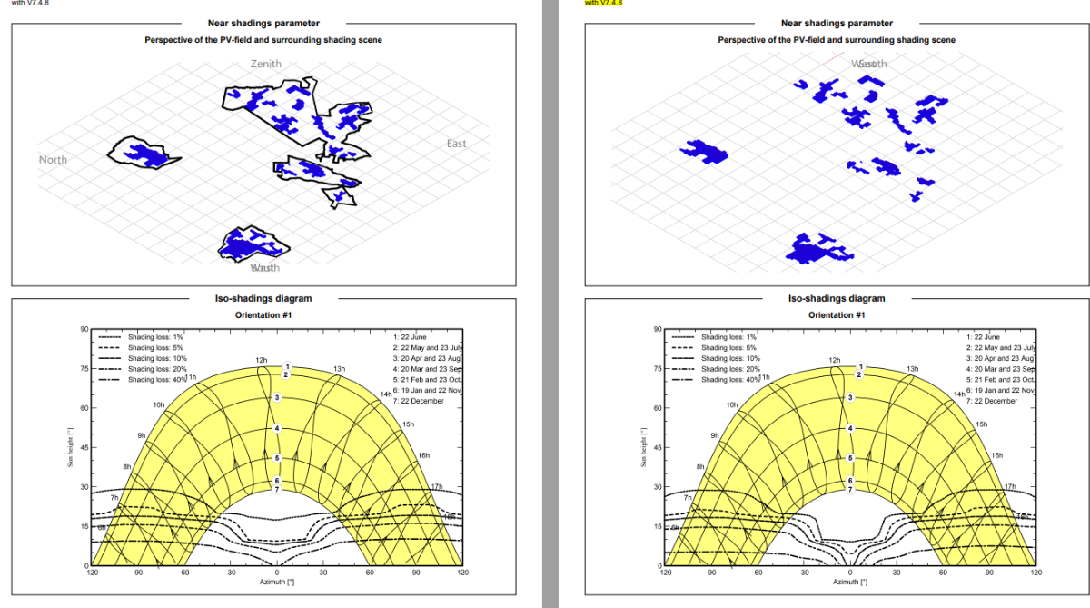
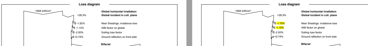
Dear User, It is kind of hard to analyse why your scenes yield different shading tables based on screenshots. For questions specific to your projects, please contact PVsyst support directly with your project : support@pvsyst.com. Regarding your first question, the iso-shadings diagrams are not identical (clearly visible on the "40%" line at the bottom which is higher on the left graph). That seems consistent with the shadings losses being higher on the left too. I won't be able to answer the second question without the actual project. Have you tried it with PVsyst 8? For the 3rd question, if the backtracking is enabled it might be possible you don't have mutual shadings at all. -
Iso-Shading Diagram when no shading object is present
PVsystUser replied to PVsystUser's topic in Shadings and tracking
I ran a similar scene (the only difference is that Tracking plane, horizontal N-S axis instead of Tilted Axis) and no iso shading diagram is generated: But I don't understand how one has tracking plane as horizontal N-S axis and the otehr one has tilted axis?
-
I have the same exact shading scene one with 30m and 10 m tall trees and one without trees, why: iso-shading diagram has loss line in both variant and they are very similar ? why the avg axis tilt is different between two variant?
-
Hi PVsyst team: Since the modules of new technologies (IBC / HJT) exhibit a very high Fill Factor. so the main contribution to this increase is the VMPP/ VOC ratio more than 86% , and resulting in lower RS(MAX) and poor low light performance. Will your team consider high fill factor module technology in future PVsyst versions? thanks!
- Last week
-
 The problem persists after I log out and restart Windows or even restart my laptop. I am using version 8.0.9.
 -
Hi, The number of inverters shouldn't impact the workaround since it was defined by the power triangle in the case of a single inverter.
-
Hello, I cannot manage to reproduce this issue. Does the issue persist if you close the window and open it again? Which version are you using?
-
Some answers to your questions: Module Mismatch Losses: Currently set to 1%. - This depends on the sample of PV modules you are installing. Not on the technology. String Voltage Mismatch Losses: Currently 0.1% - Idem, by the way this is an extremely small correction.. Module Quality Loss: Default. - This is a parameter at your disposal. You can put here what you want. But the default is based on the tolerance, it doesn't depend on the technology. LID Loss Factor: Set to 0% for N-type modules. It is indeed null for N-type cells. Otherwise the value should be set according to the manufacturer if available. For example, HPBC claims better shading performance — can mismatch losses be reduced? - This is indeed implemented in the ModuleLayout calcuation. But don't wait for a significant improvement of the shading loss ! (see the Help https://www.pvsyst.com/help/physical-models-used/pv-module-standard-one-diode-model/pv-module-reverse-lowvoltage.html?h=ibc Are there other parameters I should modify to better reflect these technologies? - If modifications are necessary, they will be in the PV module definition and modelling. We are currently studying this but we don't have definitive conclusions yet. The main workaround we can propose in the present time is to increase the Voc specified at STC when you cannot establish the one-diode model (i.e. when the RSerie cannot be specified for the required low-light performance).
-
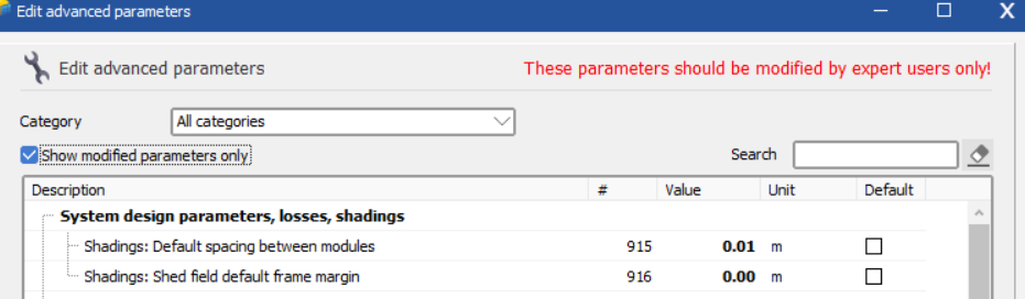
 While that is being investigated, in the past, these types of issues were caused by the default program assumptions overriding the project settings. The default value is 0.02. In the main PVsyst menu under advanced settings, set the default to 0.00 or 0.01. Import your shade scene where things are showing up correct, save, and reopen to check. The warning about tables not defined by modules is not material in most cases.
-

No import of meteo data, after selected and confirmed location
Toni replied to Toni's topic in Meteo data
Thank you for your prompt reply - I will first need to check with my system administrator. -
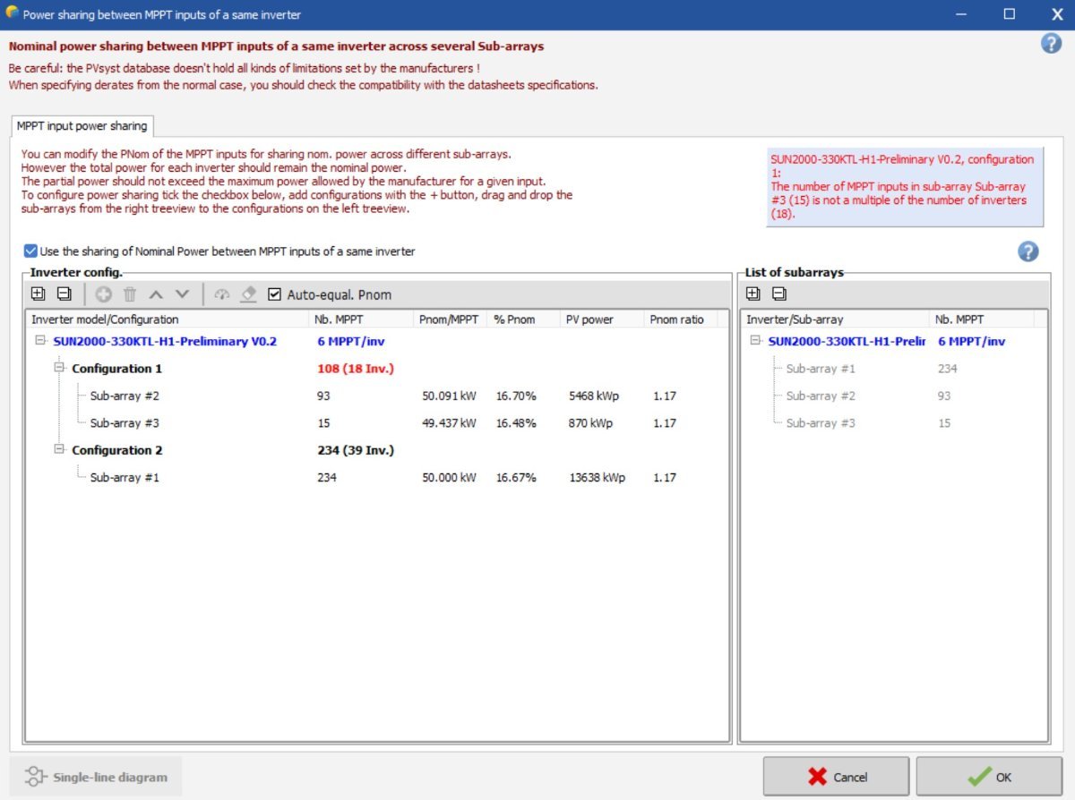
Hello, You have an explanation in the blue square in the upper right corner. In sub-array #3 you have 15 MPPTs, in a configuration of 18 inverters, thus it is not a multiple between the number of MPPTs and number of inverters. Of the 18 inverters, some would have 1MPPT from this sub-array and other would have 2, this must be premised when defining the sub-arrays and the configurations. The use of the Power sharing tool is further explained in the following tutorial:
-
 Rami Siyam joined the community
 -
Good day! Why do I get this error, please help?
-
and also please let me know is it ok to import 3D scene as a .DAE file in Pvsyst version 8.0.7?
-

No import of meteo data, after selected and confirmed location
Laurent C replied to Toni's topic in Meteo data
Hello Toni, The location of the downloaded installer might have some permission restriction, preventing you to save it. You can try by downloading directly from our website : https://www.pvsyst.com/download/latest