All Activity
- Past hour
-
 Raghad Alshaikh joined the community
 - Today
-
This temperature is meant to represent a conservative average operating temperature of the cable over time, accounting for: Ambient temperature Solar heating Enclosure or tray installation
-
 Qitter joined the community
 -
 Hello. Please send the export of your project to support@pvsyst.com so we can have a closer look at it (Project / Export the project)
 -
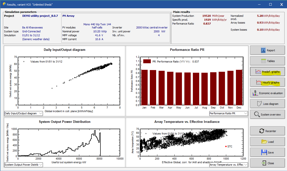
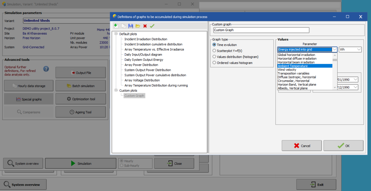
 Dear Diana, You can generate graphs and plots through the detailed results window (pre defined graphs or hourly graphs for a large amount of simulation parameters). In the Advanced Simulation window, you have additional freedom to create custom plots that also can be included in the report. Another possibility is indeed to create an Output file with the relevant parameters and do the analysis in an external tool. Kind regards
-
 Dear PVsyst Team, I would like to know whether PVsyst can generate a graph of PV power output as a function of solar irradiance and ambient temperature. Is it possible to obtain this directly within PVsyst, or through exported simulation results that correlate PV power output with these two variables? Best regards,
 -
Diana joined the community
- Last week
-
 JacksonCarroll joined the community
 -
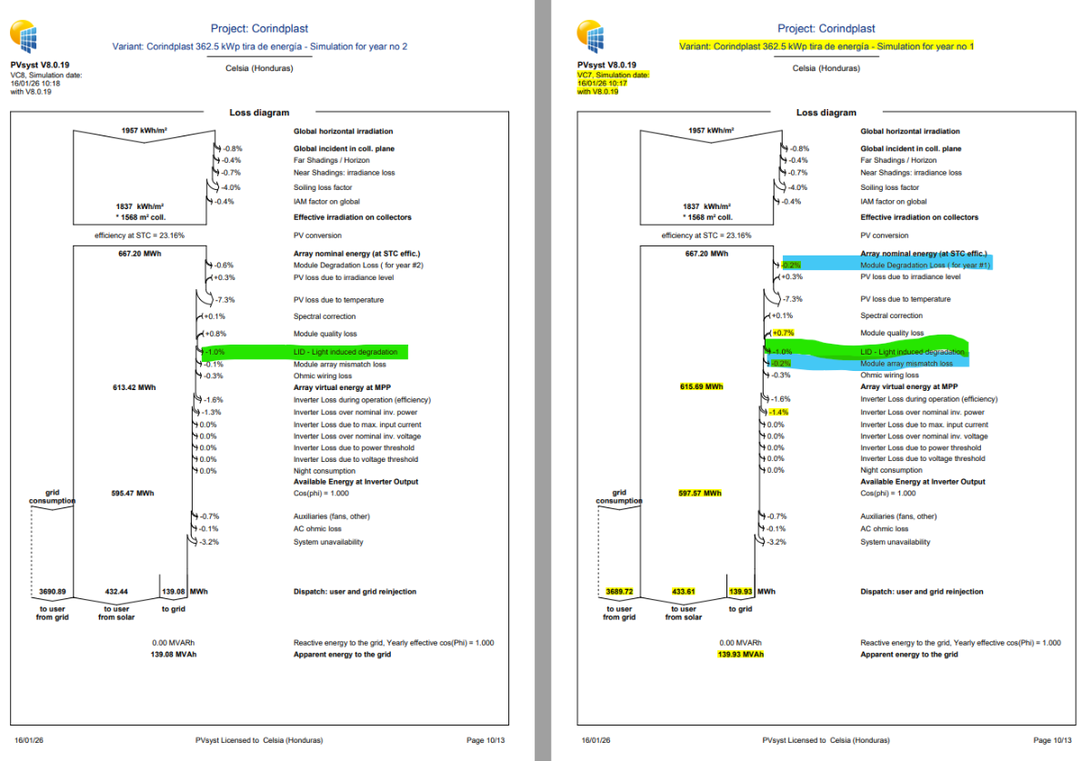
I ran a simulation with a 30-year projection and, when reviewing the loss diagram, I noticed that the LID degradation (1% in this case) applies not only in the first year, but throughout the 30 years. Is this correct, or am I misinterpreting the result? Highlighted in green. Furthermore, when reviewing the module degradation loss for year 1, in addition to the 1% LID, the model applies a degradation loss of 0.20%, which corresponds to 50% of the annual degradation rate of 0.40% from year 2 onwards. However, we also note that this same 0.20% appears in the module matrix mismatch loss. Wouldn't this mean that the loss is counted twice? Highlighted in blue. Could you clarify whether this interpretation is correct and why this is the case? Best regards,
-

LID - Light Induced Degradation and Module Degradation
Ana Sofía Lanza posted a topic in Simulations
Hello, I ran a simulation with a 30‑year projection, and when reviewing the loss diagram, I noticed that the LID degradation (1% in this case) is being applied not only in the first year but throughout all 30 years. Is this correct, or am I misinterpreting the output? Higlighted in green Additionally, when reviewing the module degradation loss for Year 1, aside from the 1% LID, the model also applies a 0.20% degradation loss, which corresponds to the 50% of the annual 0.40% degradation rate starting from Year 2. However, we also see that this same 0.20% appears in the module array mismatch loss. Wouldn’t that mean the loss is being double-counted? Higlighted in blue Could you please clarify if this interpretation is correct and why it is the way it is. Grretings,
-
The bifacial model presently available in PVsyst is based on a simplified 2-dimensional representation, with similar assumptions as the "unlimited sheds" or “unlimited Trackers” PVsyst simplified calculation. This approximate calculation may be extended to a 3D scene, provided that this 3D scene is sufficiently well represented by the "Unlimited sheds or trackers". You can read more about the bifacial model conditions in the following help page: https://www.pvsyst.com/help/project-design/bifacial-systems/2d-bifacial-model-conditions.html With multiple orientations and sub-systems with different table width, you can in version 8 create new "orientations" in the orientations window and group all the tables with similar characteristics in a sub-system/orientation, and apply the bifacial model to each sub-system in the system window
-
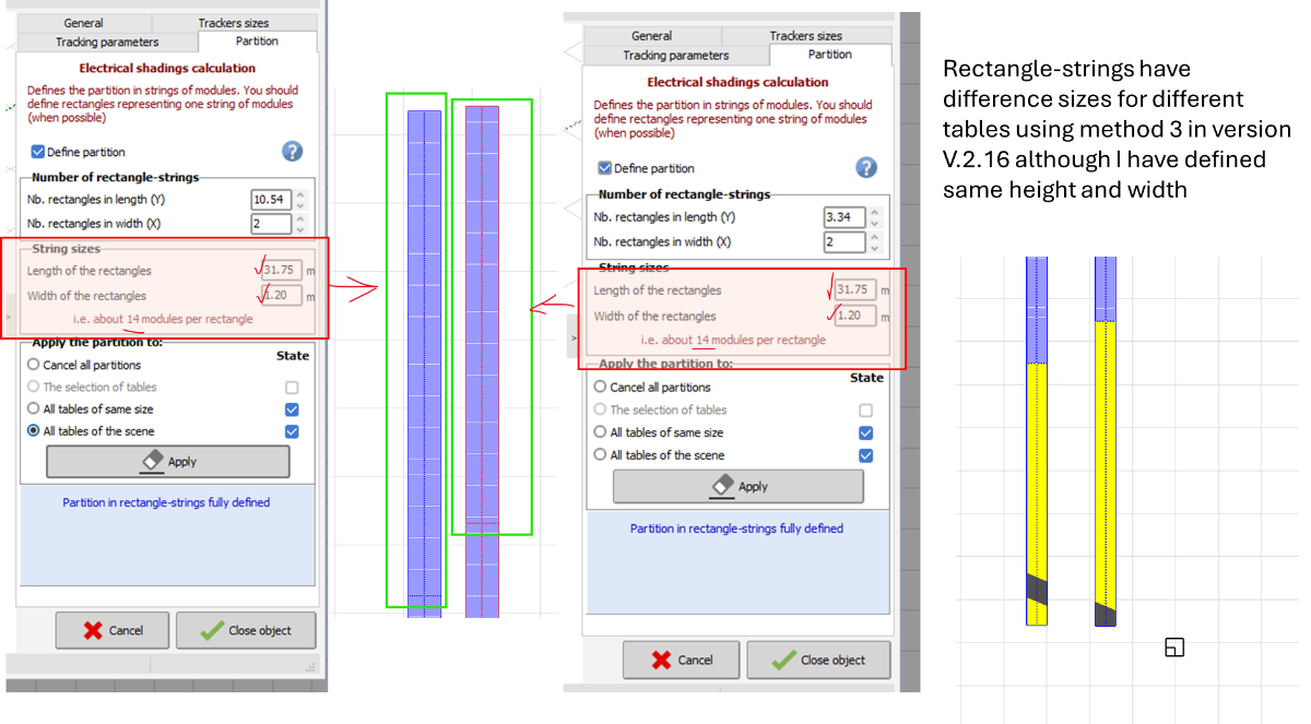
As you can see in the frames above what you have highlighted ("Number of rectangle-strings"), on your table there is a non-integer number of partitions. This means that either your tables are not consistent with the string length (can be an integer multiple or a simple fraction), or the length 31.75 is not exactly correct as a string length. The difference in length you are seeing is probably just the 0.54 and 0.34 remainder of the partitions that has shifted the partitions on the table. If your tables are just a multiple of a string length, the easiest is to use "Number of rectanlge-strings" on the tables to simply divide the string in the correct number of partitions.
-
 Recently, we encountered a mountain-based PV project using bifacial modules with layouts involving multiple tilt angles and various azimuth orientations. When attempting to simulate this system in PVSYST, persistent errors occur. Could you clarify whether PVSYST currently supports simulating bifacial PV systems on complex terrain, particularly regarding the modeling of rear-side gain? If not, are there alternative solutions available? Thank you.
-
jianke1985 joined the community
-
Hi, our team often get blank reports after we update to a new version. this does not go away on a restart and it happens to at least 4 users on our team. see below
-
Thanks! I used method 3, but there is an issue I explained in the picture below: although I have defined same rectangle sizes for rectangle string the final rectangles are not the same and I think it shouldn't be like that because 28 modules in series is valid for the whole scene.
-
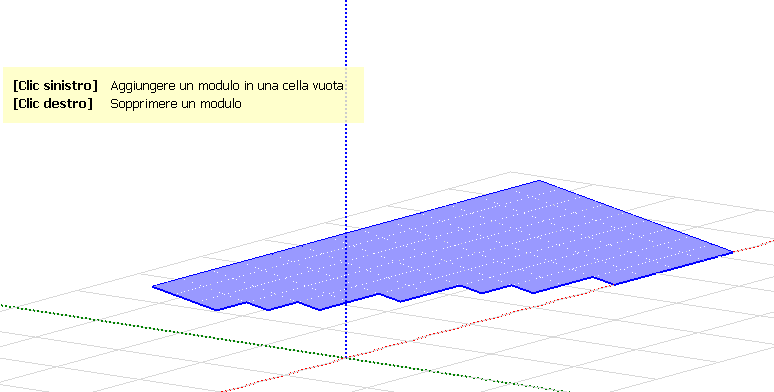
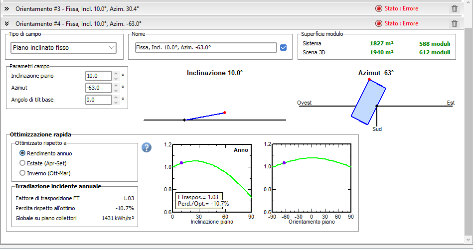
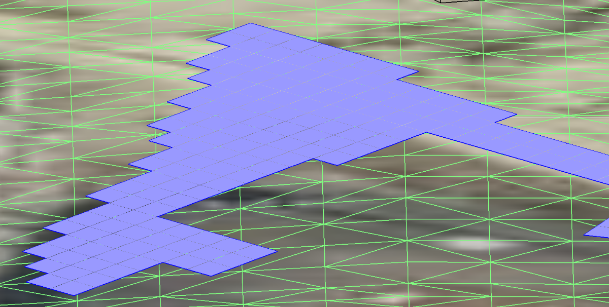
 i am gettin this stupid frustrating error that my orientation do not match by 180 degress with polygonal PV on my shadow scene even if they correspond and i not know how to solve. for be specific i have different orientation one is tilt 10 azimuth -52 one is tilt 10 azimuth -63 one is tilt 10 azimuth 30 , now i get ok with tilt 10 azimuth -52 but the other give error if they are ok . as you can see the orientation is ok it match why it give error
-
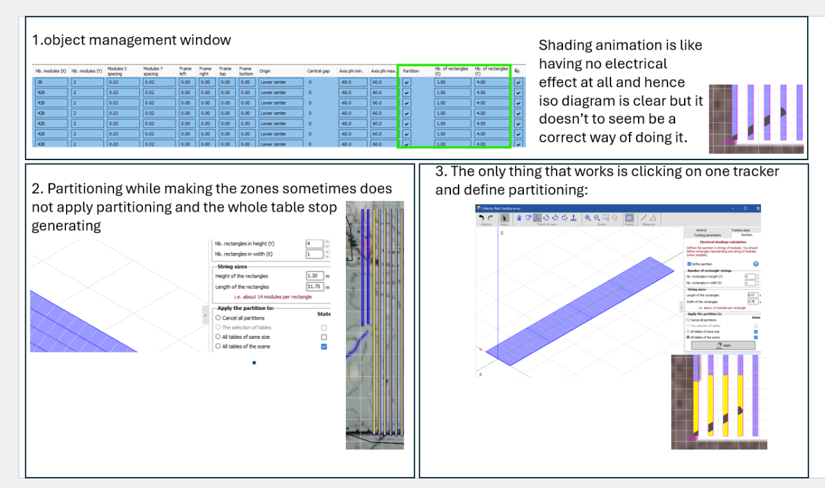
I see ! I just remembered that in this version (7.2) there is a bug for trackers. In the object management window, the number of partitions is not affected to the right variable. It is connected to the size of the partitions instead which in turn makes it not work. Please use option 3 or update the PVsyst version.
-
You are right, it was a typo, my version 7.2. Do you have any idea why my shading scene in method one does not show proper shading animation? I don't even see the dotted lines that show partitioning is done, but the shading factor table looks good for a backtracking which is 0 everywhere. I afraid that it produces zero because shading is not working at all and not because of correct partitioning.
-
Hi, There is no object management window in PVsyst 6, so I assume you are using a more recent version. Which version are you using ? I have tried to see if solution 1 had a bug in version 8.0.19, but everything works fine. You are probably correct that solution 2 may have an issue sometimes. The zone tool is rather old and sometimes misbehaves. Solutions 1 and 3 should be equivalent.
-
 Dharani joined the community
 -
 Akmal joined the community
 -
PVsyst V6.2.16 I have a 2P project, half cell with 28 modules in series (string length). I can define partitioning in 3 different ways but the results of shading animation is not the same and also the iso diagram is not the same. I included the screen shots below for all there methods. Please advise on which method is the best method to use for partitioning.
-
 shola joined the community
 -

Arev factor of BC modules in string level simulation
Luca Antognini replied to Chen's topic in Problems / Bugs
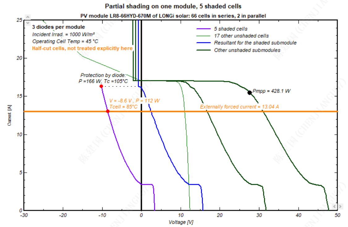
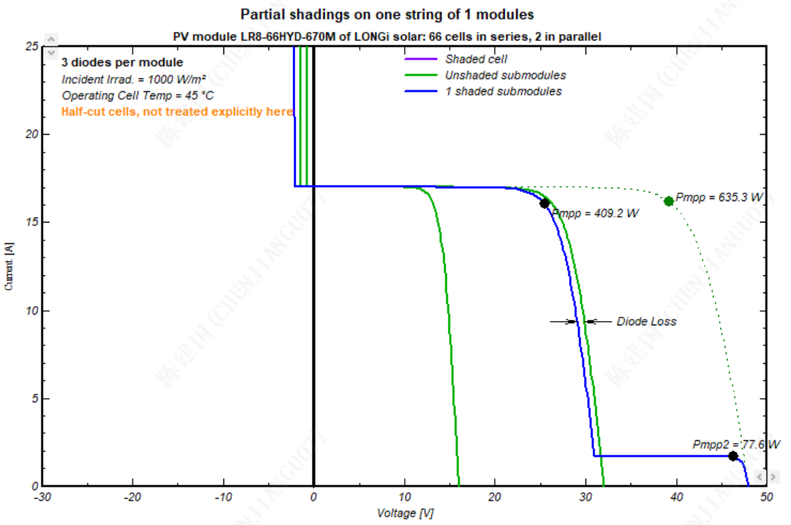
Dear Jianguo Chen, Thank you for your feedback. I share your understanding : both dialogues, with those parameters, should lead to the same results. For me the correct plot is your top screenshot, from the menu "One shaded Module". I noted that this problem seems to happen only with "Twin-half-Cut" module: If I select a "In length" module, both dialoguess give me the same results I think therefore there is a problem with the calculation of the electrical layout in this specific dialog. I will create an issue to investigate it further and fix this problem in a future version. -
 Andreacuellar26 joined the community
 -
For a TMEIC inverter we are using, the enhanced power you mention doesn't show up in the plot unless we check "Allows overpower." Is that usually the case?
-
In both versions an issue may happen for systems using the power shifting strategy with transformers losses. The issue happens when most of the PV production is diverted to the battery or most of the grid injection comes from the battery. In these cases the AC losses computation may lead to unrealistic values. This issue will be corrected in the next release. In the meantime, users are strongly advised to use PVsyst 8.0.17 for projects using power shifting.
- Earlier
-
Partitioning in Near Shading Scene
Linda Thoren replied to Surosa Naguri's topic in Shadings and tracking
Hello, You find a full explanation and a summery of common cases in the following PVsyst help page: https://www.pvsyst.com/help/project-design/shadings/electrical-shadings-module-strings/partition-in-strings-of-modules.html?h=partitio#up-to-748 -
Can anyone explain how to define the partitioning (nb. of rectangles in height and nb. of rectangles in width and also the height and width) if I have a 4 string tracker, 3 string tracker and 2 string tracker (Single axis E-W tracking) and modules in 1 portrait in a table? How will it change for landscape orientation or if I have 2 portrait orientation? How does it affect the shading scene?
-

how to simulate the back-contact solar cell module performance?
Mikael replied to Chen's topic in Shadings and tracking
Has this already been implemented? -
I am not sure I understand your question. If you are looking for PVGIS 5.3 data using the SAHARA3 model, you can just download it from here: https://re.jrc.ec.europa.eu/pvg_tools/en/tools.html
-

Tracking angle limit and effect on daytime production
Michele Oliosi replied to Nathan M's topic in Shadings and tracking
No the tracker angles are the same. The interpolation profile is only a profile Shading factor = f(tracker angle). Therefore the only changes are in shading factors (for diffuse and albedo). -
Dear Prof.André Mermoud: Recently, I have utilized PVsyst 8.0.19 for simulating the IV curves of BC modules under module-level and string-level shading scenarios. Given some inconsistencies identified in the string-level results, I wish to arrange a discussion with you on this matter. I increased the Arev factor of BC module to over 1000, and first simulated cell shading at the module level with 1 cell shaded. The results showed a 35% power reduction. When I used the string simulation tool to replicate the same number of shaded cells—i.e., a string configuration with one module per string and 1 cell shaded—the results displayed a significant discrepancy. Does it a bug? Does the Arev factor of BC modules fail to take effect at the string level? thanks! Best regards!