All Activity
- Today
-
Sorry, I can't understand that. Please send us your full project, using "Files => Export project" in the main menu. Send it by e-mail to support@pvsyst.com, and tell us in which variant you have this problem.
-

the cable loss of strings of bifacial system
Linda Thoren replied to Chen's topic in Problems / Bugs
Sorry I don't really understand what you want to. The Ohmic losses can be defined in the Detailed losses window -
 Why not group this "separate loss" with inverter clipping, near the center of the loss tree, rather than placing it at the bottom of the loss tree? Thanks.
 - Yesterday
-
 Stephan Sartor joined the community
 -
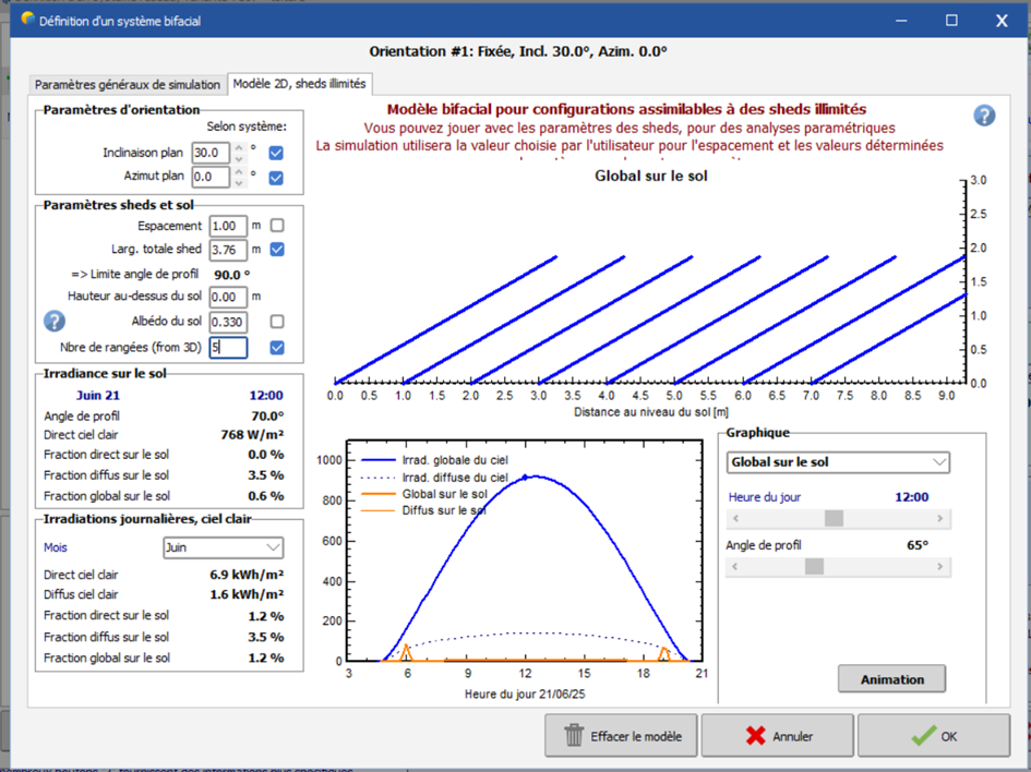
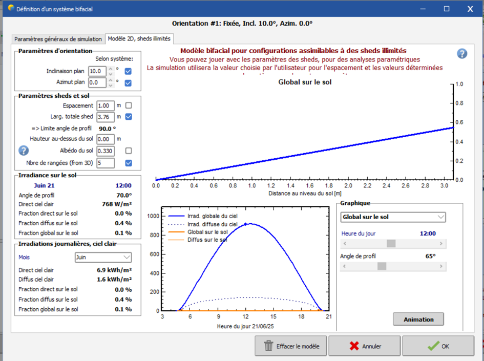
Bonjour, Dans vos exemples, l’inclinaison du toit est de 30° et 10° respectivement, et les panneaux sont-ils installés directement sur le toit incliné ? Dans ce cas, il n’est pas possible de réaliser une simulation bifaciale, car peu ou pas de lumière atteindra l’arrière des panneaux. Si les panneaux sont installés sur un toit plat avec des tables inclinées à 30° ou 10°, la simulation bifaciale est possible. Dans ce cas, l’espacement entre les rangées devrait être supérieur à 1 m si la table mesure près de 4 m.
-
Ok,I wonder if our software can be considered this.
-
 solsken energy llp joined the community
 -
the cable loss of strings of bifacial system
Linda Thoren replied to Chen's topic in Problems / Bugs
Dear, indeed, the total current should be considered. -
Bonjour, Je suis en train de réaliser une comparaison entre un système bifacial et monofacial sur plusieurs types de structures dont: une toiture inclinée à 30 degrés et une autre inclinée à 10 degrés. Or, mes résultats pour la toiture à 30 degrés ne sont pas cohérents car il y a une différence de productible entre bifacial et monofacial que je ne devrais pas avoir vu que les modules sont très proches de la toiture. De plus, pour la toiture inclinée a 10 degrés je n'ai pas ces différences. Je pense que la différence vient de la définition du système bifacial. Comment ça se fait que les schémas soient aussi différents alors que les paramètres sont les mêmes ? Par ailleurs, les scènes 3D sont identiques, mise à part l'inclinaison du toit et des modules. Comment est-ce que je peux obtenir le même schéma, c'est à dire une ligne linéaire mais avec une inclinaison à 30 degrés ? Ceci n'est qu'une hypothèse donc n'hésitez pas à me dire si vous pensez que cette différence vient d'ailleurs. Toiture 30°: Toiture 10°: Merci!

-
 bab joined the community
 -
Thank you for your response. The problem persists even when I move to the next page and select the default value. Regards.
-
Dear sir: For the bi-facial module system , when calculating the cable loss of strings, should the current on the rear side of the modules be considered in our software? thanks!
-
 Aya_SoranoAI joined the community
 - Last week
-
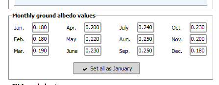
hey PVsyst. tabbing through the albedo table no longer works correctly. this is an issue after .14.
-
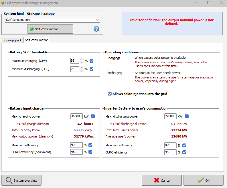
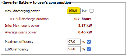
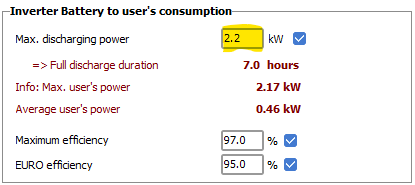
This concerns the inverter at the output of the battery pack. On the next page "Self consumption", please define the "Max. discharging power". As a first step, you can ask the default value proposed by PVsyst according to your consumption profile (checkbox on the right).
-
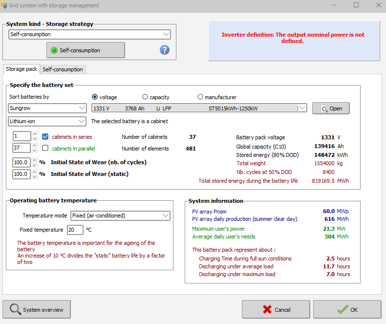
Hello everyone, When I enter the parameters for a self-consumption system with storage, an error appears that says: 'Inverter Definition: The output nominal power is not defined for a Sungrow battery with AC coupling.' I don't know what parameters I need to enter or where this parameter is located. Thanks in advance
-
In a project you can create multiple variants (both in version 7 and 8). Since the results will be for the complete system, you have to define your sub-system (for instance one inverter at the time) in separate variants. Thus, in the system window etc., define only 1 inverter and run the simulation. You can then make another variant of your project with the second inverter etc.
-
For your suggested workaround, how can I do that in PVsyst 7?
-
Hello, At the moment, PVsyst only provides yield and performance results for the complete system as a whole. Viewing results per inverter is not yet available (though it is on our roadmap). If you need results for each inverter separately, the current workaround is to simulate each inverter as its own variant.
-
Is there a way for me to view the result of a simulation per inverter stated in the System? For instance, the project has three inverters. I want to see the simulation result for each inverter that I placed in the csv file (time series data). Thank you.
-
 icicle joined the community
 -
 Sunrays Energy LTD joined the community
 -
 Bengar9 joined the community
 -

PVSyst unexpectedly closes during long batch runs
Laurent C replied to Andrés Fernández's topic in Problems / Bugs
Dear Andrés Fernández, Please email us also at support@pvsyst.com : your PVsyst LOG files (using menu <File> <Export logs>) your project files (using PVsyst menu <Export projects>) so we can try to reproduce the issue you reported. Best regards. -
 rogoya7403 joined the community
 -
Thanks to this article I solved my problem.
-
 Christine Parr joined the community
 -
OK, u are welcome
-

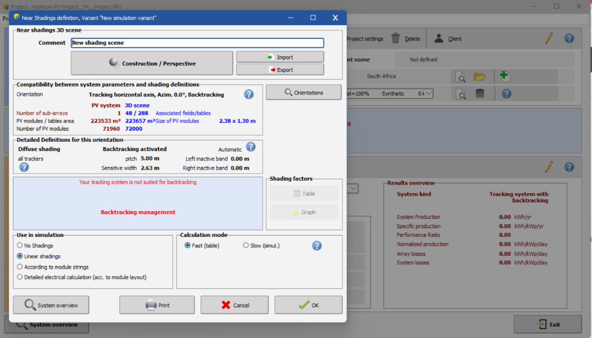
Backtracking Management Assistance Required
ASZulu replied to ASZulu's topic in Shadings and tracking
Hi Michele, 🙂. Thank you so much for the swift response. Yes, I was also confused by the same thing. I have shared the project file via email, as requested. Your assistance and guidance is really appreciated. -

Backtracking Management Assistance Required
Michele Oliosi replied to ASZulu's topic in Shadings and tracking
Hi, this is strange. NS axis trackers (whether 3D scene or using the “unlimited trackers” optimization) should work without issue. Can you send your project (use the export button in the project window to generate a zip archive with all necessary files) over to support@pvsyst.com ? Or share a snapshot of the disposition of your 3D scene. This will allow us to look into it further. -
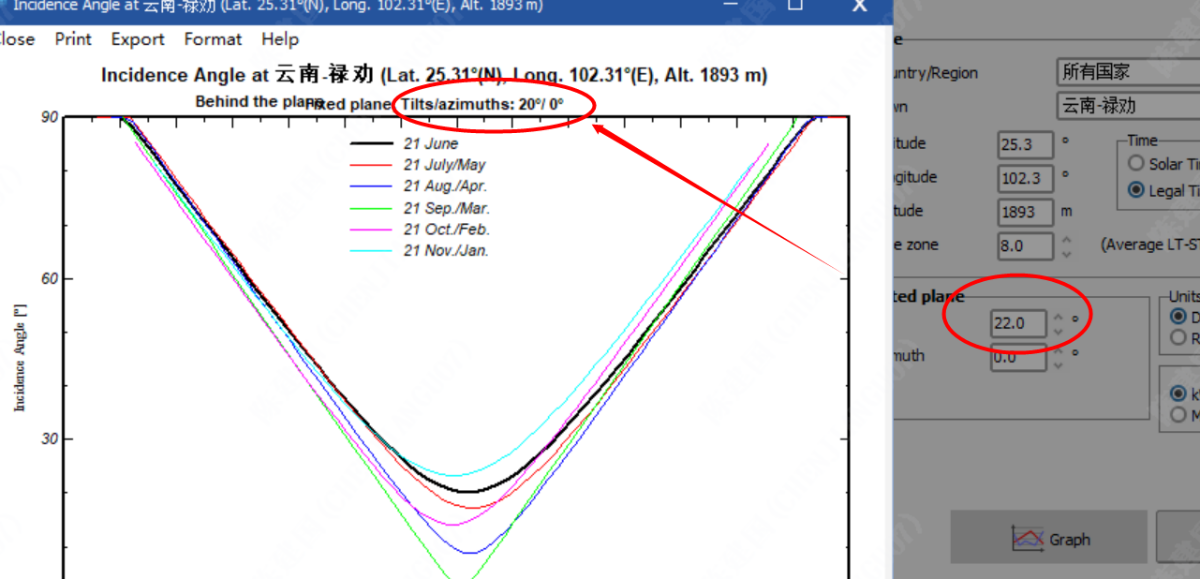
Yes sorry, this is an error in the graph title. The values for the curves calculation are indeed those specified in the dialog. Thank you for pointing this out. We will correct this for the next version 8.0.16.
-
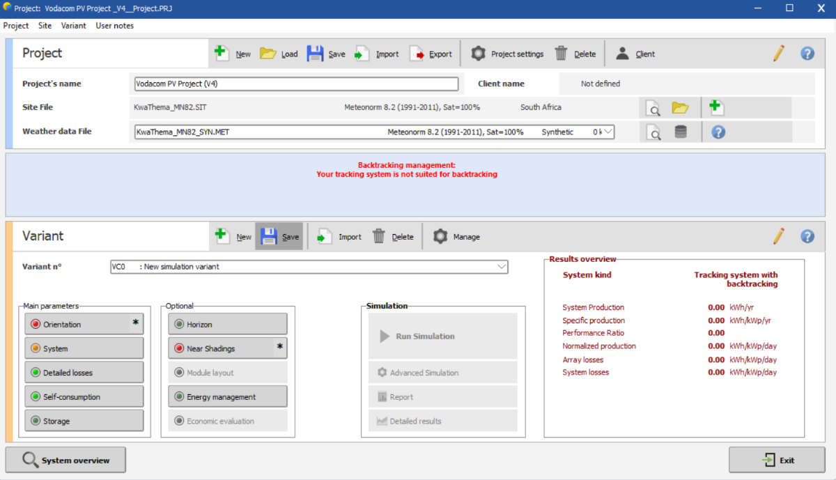
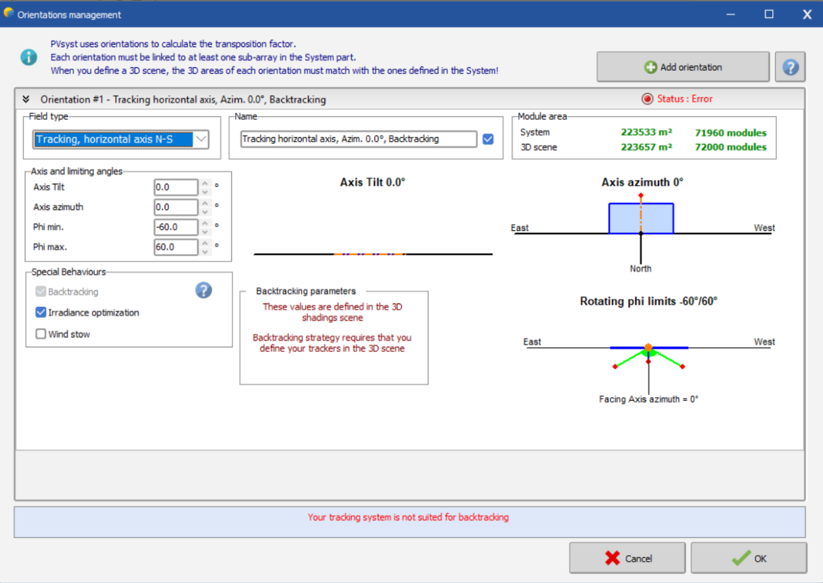
Hi everyone, 🙂! As a fairly new user of the software, I needed assistance with the Near Shadings for the simulation I am running. I keep getting the error stating "Backtracking Management: Your tracking system is not suited for backtracking" as shown below: Initially, I used "Unlimited Trackers with Backtracking" but noticed that PVsyst would not let me create a shading scene with this option/tacking system. This then resulted in the use of the tracking along the horizontal axis (with backtracking activated, and an azimuth of 0 degrees) as seen below. I am not sure how to proceed as the first screenshot above displays confirmation that backtracking has been activated from the "Backtracking Management" menu within "Near Shadings" and this is the only obstacle left before being allowed to run the errorless simulation. I have shared a screenshot of the System Overview below for context and convenience. Appreciate any and all help I can get on this. Thank you.
-
Dear sir: I found that the inclination angles of the two are not the same. Is it a bug?THANKS
-
Hi, The execution of the shading factor calculation may take some time, and has to be evaluated at each simulation hour. For speeding-up the simulation execution, we calculate a table of shading factors for specific sky orientations (every 10° in tilt and 20° in azimuth). Then at each step, the simulation can calculate the exact sun's position, and interpolate in this table ("Fast" shadings calculation"). This table is also used for the elaboration of the shading factor on diffuse and on albedo integrals. You find more details in our help, for instance the treatment of the Beam component: https://www.pvsyst.com/help/project-design/shadings/calculation-and-model/treatment-of-the-beam-component.html and the shading factor table: https://www.pvsyst.com/help/project-design/shadings/calculation-and-model/shading-factor-table.html Kind regards