All Activity
- Past hour
-
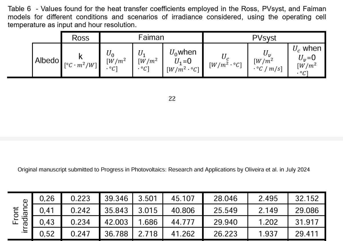
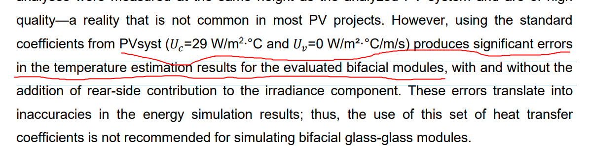
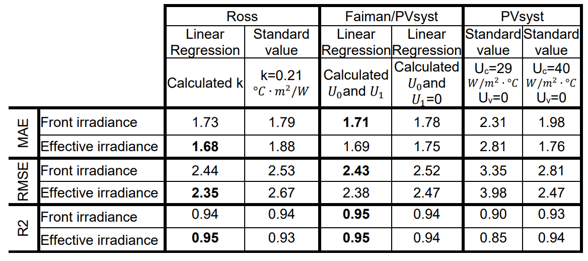
Dear Chen, Thank you for forwarding this article, it is an interesting study. However, most of the conclusion is misleading: PVsyst doesn't use the Module temperature in the simulation but rather the cell temperature. The cell temperature is not measured directly in this study (it would require placing temperature sensor inside a module during fabrication). The difference between module temperature and cell temperature is corrected for in section 3.4 and the coefficients Uc and Uv are recomputed there. These values (table 6) correspond physically to what should be used in PVsyst. The range found is ~[29-32] which is reasonably close to our default recommendation. Note that the authors also mention that the model used to compute cell temperature has not been validated for their specific technology, so the results should be taken with a grain of salt.

-
 Hi all, I have to run a simulation in PVsyst in order to compute the shadowing impact created by the presence of three wind turbine aerogenerators located within the layout design of an agrivoltaic PV plant. To do so, I am well aware of the fact that I can import in the PVsyst tool Near Shading 3D scene a .pvc file (from PVcase) of the layout which can include the 3D shadowing items of the 3 wind turbines with the aim to compute in the simulation the impact of the shadows generated by those turbines with respect to the PV plant producibility. In this regard, I would like to know: - if the software quantifies such shading losses in the loss diagram under the voice Near Shading Losses. If not, please clarify in which voice they are allocated in the loss diagram -if there is some kind of way to compute the impact of the shadings generated by the wind turbines in a daily/hourly/monthly formats to understand for example through the year in which periods of time (days, hours) the shading effects is more relevant Please let me know if there is the need of any additional information that could be helpful to provide an answer to my questions. Thank you in advance. Vinh
 - Today
-
Are we making any progress to including an inverter in a stand-alone system? Thanks!
-
 Fei Y joined the community
 -
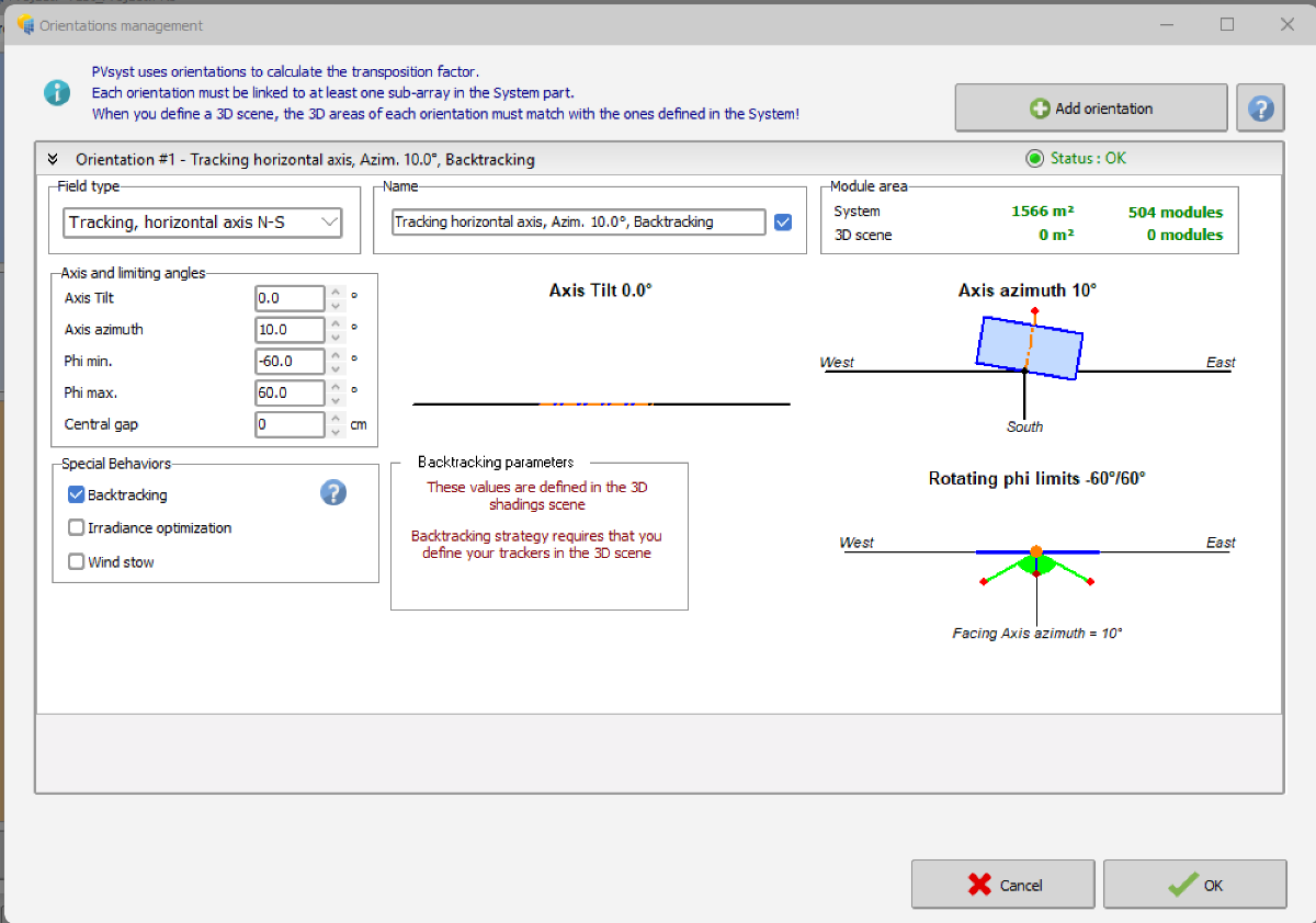
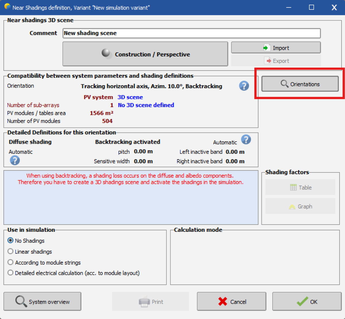
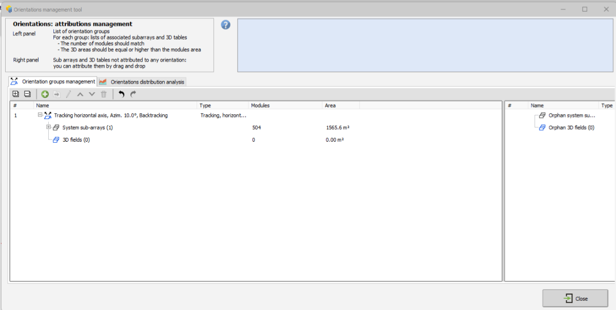
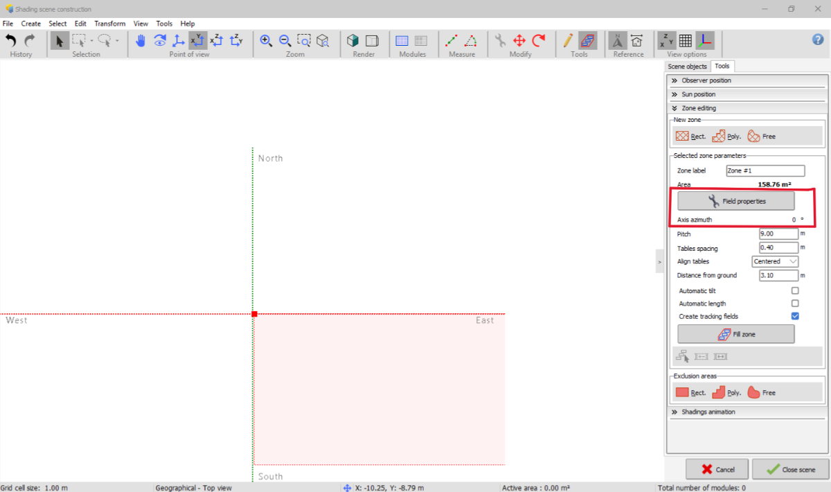
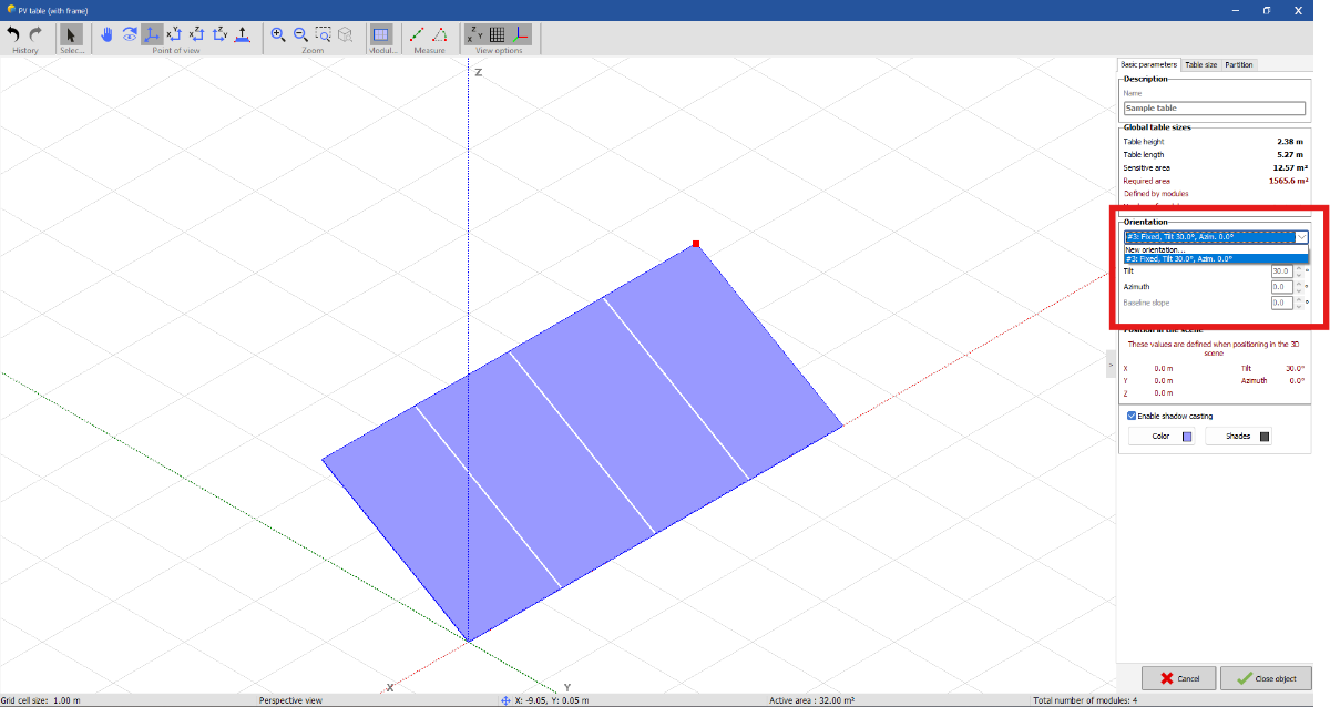
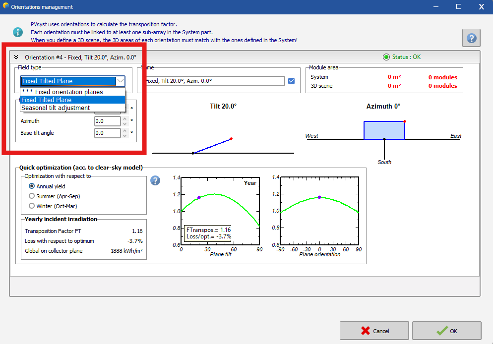
 Hello, I'm having trouble with the "Orientation" objects in PVSyst 8. In the Orientation page I've created a Tracking horizontal axis N-S item with Backtracking activated (see image 1). This orientation is correctly displayed both in the "Orientations" menu of the Near shading 3D scene (see image 2) and in the Orientation management tool within the 3D scene "Construction and perspective" environment (see image 3). However, when I create a new zone in the 3D scene and I click on "Field properties" (see image 4) --> "Basic parameters", I do not see the Orientation I've defined but only a Fixed, Tilt=30°, Azim=0° orientation I've not created (see image 5). Furthermore, if I click on "New orientation..." I'm unable to define any Orientation other than "Fixed Tilted Plane" or "Seasonal tilt adjustement" (see image 6). Any help would be greatly appreciated.
-

Finding out the reflection caused by the solar panels
Robin Vincent replied to Adeline's topic in Simulations
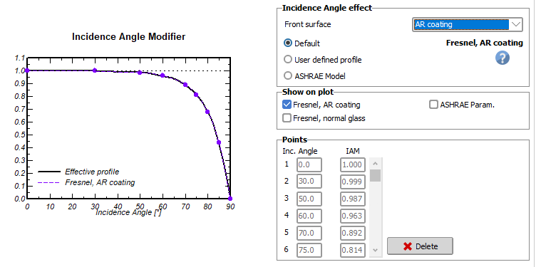
Regarding the direction, as Michele mentioned, the best way would be to find a dedicated glare tool. Alternatively, you could compute the direction yourself based on the sun position and the modules orientation. For the quantitative part, you could use the IAM values of your PVmodule, the incidence angle and the incident irradiance to estimate the reflected energy.
-
Gridshape joined the community
-
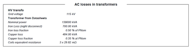
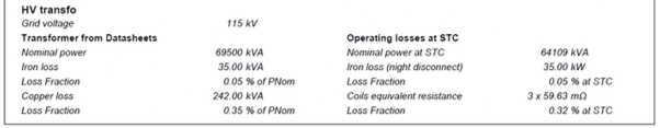
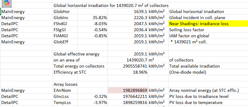
 PVsyst V8.0.12: Hello, the "Operating losses at STC" sections of the PVsyst V8 output PDF report have disappeared (!). See below screenshots as example (V8 screenshot is missing the section; V7 screenshot contains the section on the right-hand side). (NB: Please note the value for Iron Loss Fraction in one of the screenshots is incorrect, as there was a typo in the input. This rapid example was for screenshot purposes only.)
-
There are common instances when we would apply different "soiling" assumptions (which includes dust, snow, etc.) for different PV module types (e.g., monofacial, bifacial). We would like the ability to apply a different set of monthly soiling values for each subarray in PVsyst V8. This would resemble the subarray dropdown menu for the MQA factor in Detailed Losses. Is it on the development roadmap? Thanks.
-
I would like to simulate 2 MW floating PV system, how to start ?
-
 Shurouq joined the community
 -
P.S. I am referring specifically to this message:
-
 tomomi joined the community
 -
Dear PVsyst team: I saw an article in the literature that mentioned a comparison between the settings of UC and UV and actual simulation tests. Can we see if there is still a need to optimize UC for bifacial modules? thanks de Oliveira A K V, Braga M, Naspolini H F, et al. Validation of Thermal Models for Bifacial Photovoltaic Systems under Various Albedo Conditions[J]. ESS Open Archive eprints, 2024, 63: 06323163. https://onlinelibrary.wiley.com/doi/abs/10.1002/pip.3892 CTG_PIP_Temperature.pdf
-
 trevor ashala joined the community
 -
 M.Danyal joined the community
 - Yesterday
-
EarrNom and all resulting energy are not shown correctly when exporting loss diagram values from the report. The report itself is correct, but the exported values are not.
-
Hi, I'd like to specifically request a 10-min. editing time as an incremental (and meaningful) improvement. Thank you!
-
PVsyst V8 Problem Statement: How to apply spectral adjustments to certain subarrays (containing certain PV module cell types) and *not* to others? Ideas (example only): 1.) This could be handled in the PV module PAN file, through a checkbox which (if checked) will apply spectral adjustments IF the tab in Detailed Losses is applied 2.) This could be handled as a dropdown menu for each subarray on the spectral adjustment tab in Detailed Losses, similar to the MQA factor subarray dropdown menu, where you can toggle on/off spectral adjustments for each subarray 3.) (Least favorite option): If the spectral adjustment tab of Detailed Losses is applied, it could automatically apply spectral adjustments onto the specific technologies involved in each subarray according to PV cell technology type. This is the least favorite option, because not all PV cell technologies should use spectral adjustments (e.g., single-junction Si-based technologies). Conversely (and preferably), Options 1 and 2 above would allow the user to *only* apply spectral adjustments onto the (sub)set of PV cell technologies in the applicable subarrays which require spectral adjustments. Thank you!
-
 soljoji123 joined the community
 -
The 1100UD is one inverter module that is typically installed with other modules in a single PCS, like the 4400UD-MV. You will have four mppts with the 4400, each 1100 is one mppt as stated above.
-
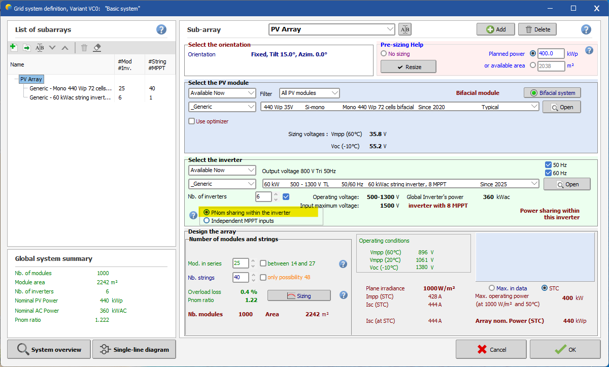
Dear Nikoloz, It seems that the inverter you want to use is a central inverter with only one MPPT. This means all strings connected to it must be identical. So, you don’t need to worry about the MPPT definition. In PVsyst, just select the configuration “PNom sharing within the inverter” (see below). Then, you only need to specify the number of inverters. Regards,
-
Dear Ishan, First of all, the Unlimited Tracker represents an idealized PV table layout, with all rows having exactly the same length. Most likely, your 3D scene doesn't follow this idealized representation. Could you please send us your project by email at support@pvsyst.com, so I can check it and explain why you're seeing these differences? Regards,
-
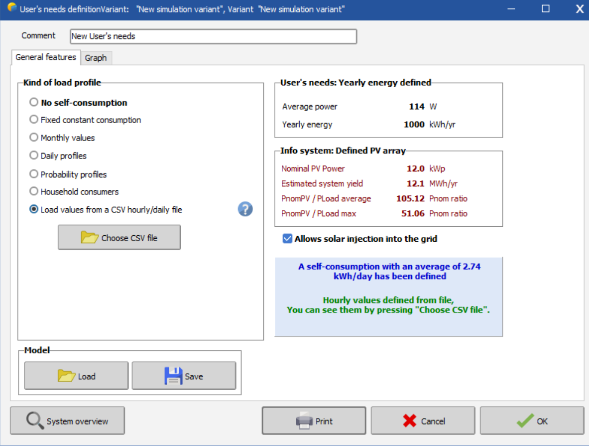
Hi, I designed a solar system to see what percentage of generated solar energy can be self consumed. I loaded values from a CSV file. Where can I see graphs or table to indicate the amount of energy self consumed, and the amount of energy imported and exported from the grid?
-
 Johann joined the community
 -
 Nikhil Pal joined the community
 -
 Steve_NO joined the community
 -
Hello I have such question. does anybody had used modular inverters ? Sungrow_SG1100UD what about this inverter ? when I uploaded OND file in PVsyst there is no information about MPPTs, there is some error with dtasheet ? I have to make desighn of 100MW plant but how to organise strings in mppts?? here is datasheet link https://en.sungrowpower.com/productDetail/4102/1-x-modular-inverter-sg1100ud-20
- Last week
-
IRev is calculated according to the expression mentioned above, by neglecting Rserie (put Rs = 0). This expression gives the IRev as a function of a specified voltage. Iph is the short circuit current for this shaded cell.
-
While simulating project with identical capacity, components, and loss factor , PVsyst has generated variable generation( E grid MWh) results for Unlimited tracker mode and the 3D scene mode . Egrid MWh Near Shading loss : Irradiance Unlimited Tracker 1438860 -1.8% 3D scene 1481095 -2.4 % I want to understand how PVsyst is generating variable results for Unlimited tracker and 3D scene mode which should not be case for identical project parameters(Pitch,1P,Other loss factors). What are the factors resulting in this variation .
-
OK IRev = Iph +aRev *V,for aRev=800mA/V^2, 800/1000*(-5.2)*(-5.2)= 21.632 (A) ;the externally forced current is 7.93A; how to calculate IRev? thanks
-
In PVsyst, the model for the reverse characteristics is this quadratic expression. This corresponds rather well to the reality, but this is a rough approximation. By the way the values of this model have a quasi null impact on the PVsyst simulation results. Now the term (Rserie * I) is indeed a little contribution (perhaps it should not be taken into account, we will check). You can forget it.
-
 If it still doesn't work you can always model it as I have above 🙂 The gaps will not matter for bifacial calculations, they are not used. The user defines the transparency factor manually which takes into account gaps in structure, modules, etc. So I'd either model as I have or increase the gap in your method if the suggestion above does not work.
 -
Select 'Disable field interpenetration check' from inside shading scene and see if that works
-

Finding out the reflection caused by the solar panels
Adeline replied to Adeline's topic in Simulations
Thank you for the fast response! is it possible for you to share some ways to indirectly estimate? Yes! I am looking for the purpose of glare regulations