All Activity
- Today
-
Hi, I have been trying to simulate with the subhorly opcion but it reminds not available for selection (in a light gray).

-

Arev factor of BC modules in string level simulation
Luca Antognini replied to Chen's topic in Problems / Bugs
Hello, In the simulation, the Arev factor and reverse characteristic is not influenced by temperature nor irradiance level. Is that what you're asking? Please consult also our Q&A on how to simulate those device in PVsyst in the current version: -
No specialized implementation yet, but you can consult our recent Q&A on the topic to understand the impact of BC cell and what workaround can be put in place to simulate them in PVSyst:
-
Limitation of pan file for BC and HJT module
Luca Antognini replied to Chen's topic in Problems / Bugs
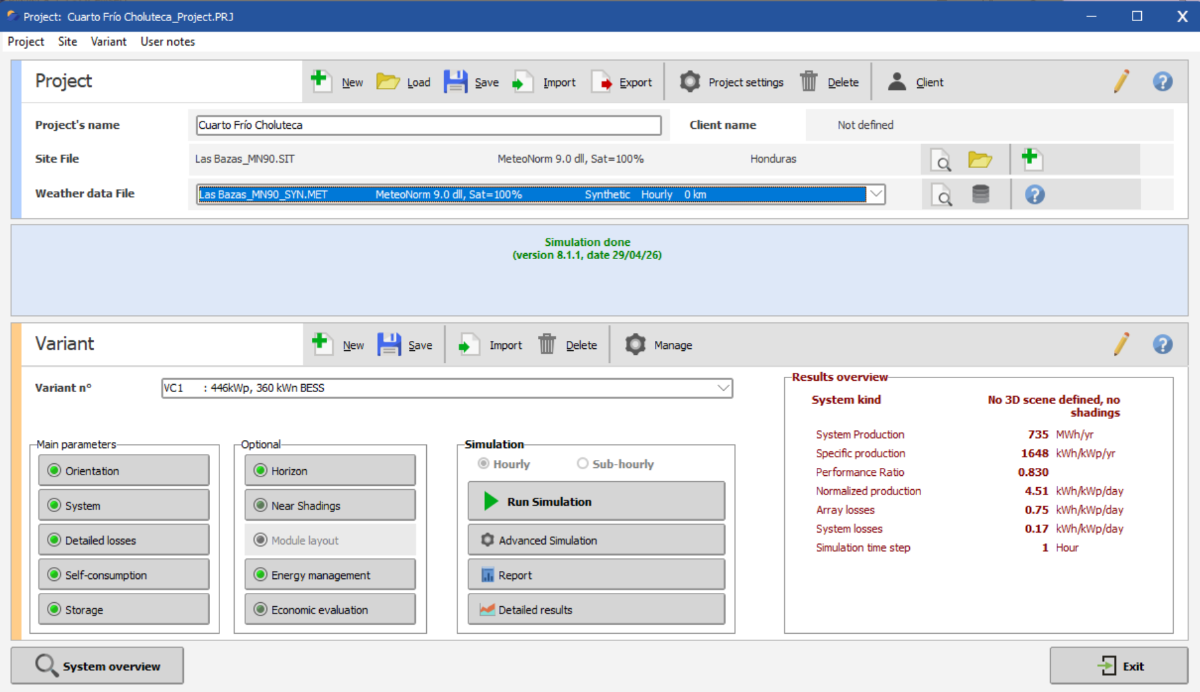
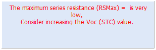
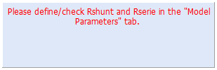
We research the topic (see our abstrac from EUPVSEC) but no new implementation at this stage. For the moment we still propose the following workaround: Problem for one diode model parameter determination with High fill factor PV modules: When entering a PV module in the database with a very high Fill Factor (above ~ 82-83%), or equivalently very high Vmp/Voc (above ~86%), PVsyst might not be able to find suitable parameters for the one diode problem and the following messages might appear: or This comes from the fact that PVsyst needs to find parameters that simultaneously reproduce several constraints and there might not exist a mathematical solution. This is a known mathematical problem, and more information is available in our dedicated publication : https://www.pvsyst.com/en/company/publications/ The solution we propose at the moment is to increase slightly Voc until PVsyst is able to find a solution. Note well that this does not impact the MPP, therefore the simulation results remain mostly unchanged by this small work around. PVsyst will find the minimum increase of Voc required if you do the following: 1) Go in the Tab "Model Parameters" 2) Check the box to get the default value of Rshunt: A pop-up will appear informing you of the impact on the relative low-light efficiency. Click Yes to close it. 3) Check the box to get the default value of Series resistance. Another pop-ip will appear informing you that in order to find a series resistance suitable with a relative low-light efficiency of -3% (the default value we suggest), PVsyst will need to increase the shunt resistance and possible the Voc value. Again click Yes to accept
-

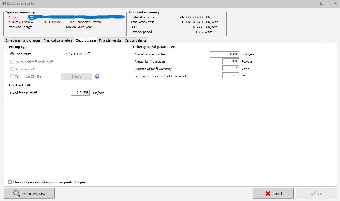
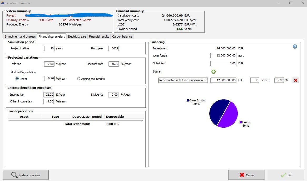
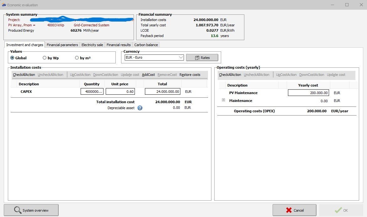
Economic evaluation with fixed amortization loan
Hizir Apaydin replied to Nikos's topic in Simulations
Dear Nikos, We have replied to you in detail by email. We remain at your disposal should you need anything further. Best regards -
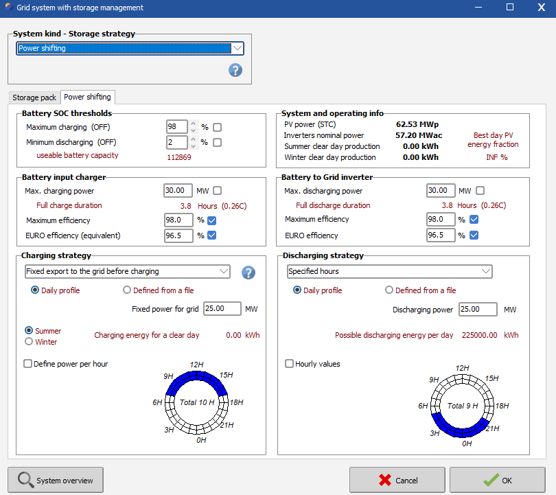
 There is a bug that changes the value from 25MW to 25000MW. This leads to a battery that never charges, since the production never reaches this value. We will try to fix this as soon as possible, but in the meantime you could set the value to 0.025 to get the correct behavior. NB: the value displayed in the report for the charging power is also erroneous, as it is displayed in MJ/h instead of the indicated unit.
 -
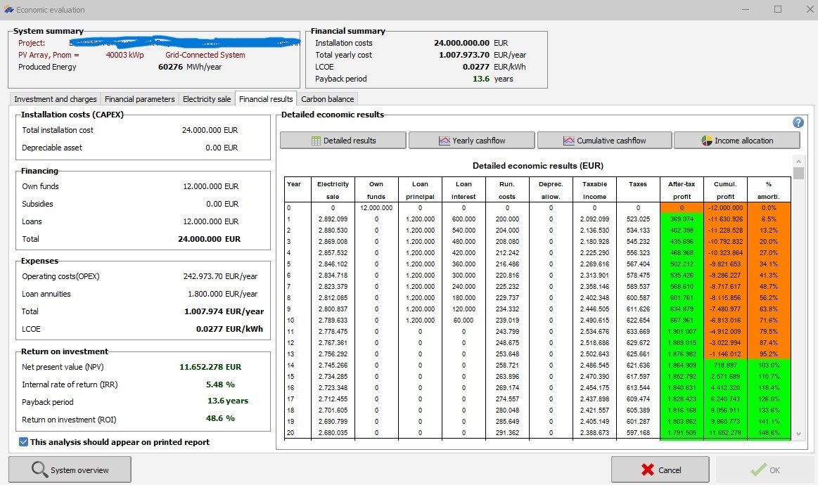
Hello, Please explain how After-tax profit, Cumul. Profit and % Amortization are calculated in the attached case. Thank you in advance!
-
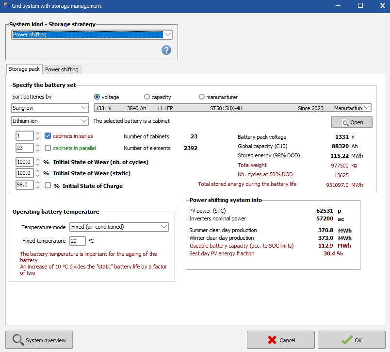
 Hi everyone, I am facing difficulties to configure the storage setting for charging strategy "Fixed export to the grid before charging". For context, my hybrid PV + BESS plant size is: PV 62.5 MWp / 50 MWac with BESS usable capacity 25 MW / 100 MWh. Grid Lim = 50 MWac, with this understanding, for whatever value of PV production exceed 50 MWac e.g. (57.20 MWac - 50MWac = 7.20 MWac) shall be charge to the battery. But it did not show up as what i expect. The section configuration for System and Operation Info indicates my "best day energy fraction is INF%" how to solve this issue? Based on the report produced, it seems the battery is only discharge during the discharge window as config in Discharging Strategy. And not charging for the remaining days. Request for expert support to advice on this misunderstanding or error. Solarvest ITA
- Yesterday
-
 David Rodriguez joined the community
 -
 Sunrise EnergySolution joined the community
 -
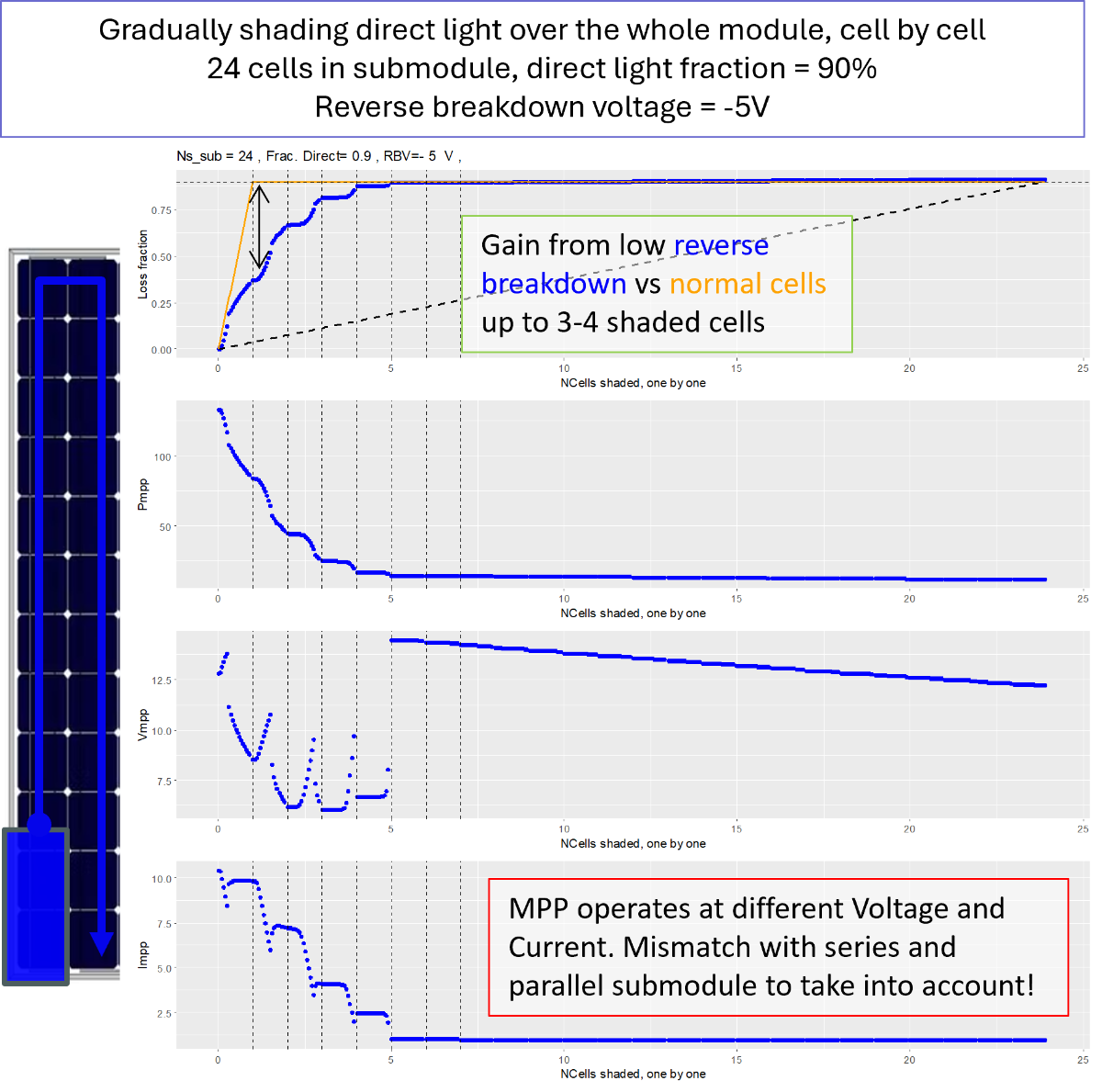
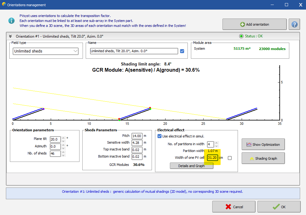
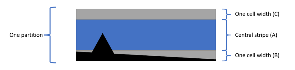
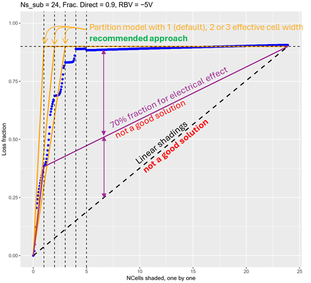
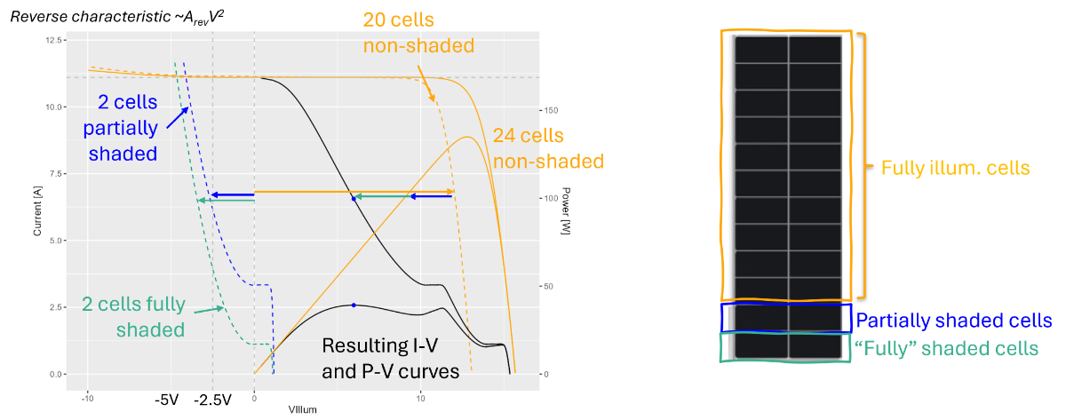
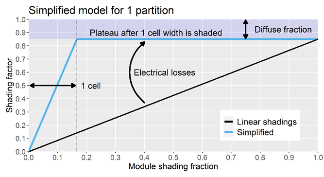
Summary: - Low reverse breakdown solar cells have a stronger shading tolerance than conventional modules in situations where less than 3-4 cells are shaded. - In the case of mutual shading of large systems with a row arrangement, we recommend to approximate their behaviour in PVsyst using the shading model of the "Unlimited sheds" or "Unlimited Trackers" orientation, using as input a cell width 2-3 times larger than the real value. - In the very specific case where shading on 3-4 cells or fewer occurs very often we have no precise recommendations. But since those situations occur rarely in large row-based systems, we recommend to stick to the usual recommendations of usage of the partition and module layout model. Since shading situations with 3-4 shaded cells happen rarely in large system, we estimate that neglecting this effect will not lead to significant errors in the yearly yield calculation. Therefore, PVsyst currently handles PV modules with IBC cells in the same way as other crystalline Si modules. Nevertheless, we intend to include the special behavior of IBC cells into our models, in order to account for this small improvement. The current roadmap foresees the availability of this feature by end of this year. In the meantime, the above described workaround should allow to approximate the results in a satisfying way. Q&A index: 1) What are the common misconceptions when using PVsyst to simulate low reverse breakdown voltage (RBV) solar cells? 2) How does the shading tolerance of PV modules featuring low RBV cells physically work? 3) How to simulate low RBV cells in PVsyst using the "Unlimited sheds" or "Unlimited trackers" case? 4) How to simulate low RBV cells for other shading scenarios? 5) What are the limitations of PVsyst shading models for 3D scenes when simulating low RBV cells and what are the recommendations? 6) Why modifying the electrical shading factor is not recommended to simulate low RBV cells? 7) Why modifying the Arev factor in the .PAN file does not improve representation of low RBV cells? - - - - - - - - - - - - - - - - - - - - - - - - - - - - - - - - - - - - - - - - - - - - - - - - - - - - - - - - - - - - - - - - - - - - - - - - - - - - - - - - - - - - - - - - 1) What are the common misconceptions when using PVsyst to simulate low reverse breakdown voltage (RBV) solar cells? We noted a few points of misunderstanding in the way the community tries to run PVsyst simulations for low reverse breakdown voltage (RBV) solar cells, such as some back-contact cells technologies. This answer aims at correcting those views, stating clearly what can or cannot be simulated in PVsyst at the moment, and how. Some common incorrect beliefs around this topic are: /!\ That each cell acts as its own bypass diode and therefore shading a cell doesn't lead to additional electrical shading losses. /!\ That, following the previous belief, the partition model can approximate the behaviour of those cells by setting a large number of partitions: This, however, strongly underestimates the voltage and current mismatch between the submodules. /!\ That it is possible to adjust the electrical shading fraction to fit those cells' behaviour: As we will see, this is in reality a poor fit to the real behaviour. /!\ That the module layout model is accurate for any arbitrary shading scenario: It is actually agnostic to the number of shaded cells, which matters for the precise description of low RBV cells. These misconceptions are related both to the understanding of the physics of the low RBV cells as well as to the understanding of the limitations of PVsyst shading models. Therefore we shall cover both topics: 2) How does the shading tolerance of PV modules featuring low RBV cells physically work? Low RBV cells have the advantage of allowing significant current to flow already at moderate reverse voltages. According to the literature, those cells allow a current around ~10 A at a reverse voltage of around -5.0 V to -2.5 V. This is indeed analogous to the working principle of a bypass diode in parallel with a string of cells (submodule), except it would be as if each cell possessed its own bypass diode. However, as in the case of a regular bypass diode, the reverse operation of a low RBV cell leads to a voltage loss. For example, in a string of 24 low RBV cells under illumination, a fully shaded cell will operate at around -5 V, reducing the total voltage of the string. Increasing the number of shaded cells drastically reduces the voltage of the string: Number of shaded cells Number of remaining illuminated cells String voltage 0 24 14.4 ( ~0.6 x 24) 1 23 8.8 2 22 3.2 3 21 string operates in reverse => bypass diode activation This simple estimation shows us immediately that the benefit of the low RBV technology is only present in shading scenarios where only a few cells (3-4) are shaded, due to the significantvoltage loss created by those cells. In shading situations where more cells are shaded, low RBV cells perform the same way as regular cells due to the bypass diode activation. To be more rigorous, we show in the following figure a more precise computation resulting from the summation of the I-V curves of each cell of a submodule of 24 cells. For this example, the direct light is fully shaded for one cell and partially shaded for another, while the remaining cells are fully illuminated. This shows how voltage is loss in the shaded cells and how the MPP can abruptly shift to lower voltages. The next figure is created using the same method, gradually varying the number of shaded cells: Compared to a regular cell (in orange), which features a sharp rise in losses after a single cell is shaded, the low RBV technology mitigates these losses when less than 3-4 cells are shaded (as expected from the simple estimation). Above this, the only power remaining comes from the unshaded diffuse light, as for regular cells. Moreover, we note that the operating point (Impp, Vmpp) follows a distinctive pattern for this technology. If this submodule is connected in series (parallel) with unshaded submodules operating at another current (voltage), the benefit of the low RBV technology will be lost because an electrical mismatch loss will occur. An example is the common case of twin half-cell modules, where the top supbmodule is connected in parallel to the bottom one: In a shading scenario where a shadow comes from the lower part of the submodule, the voltage mismatch created between the top and bottom submodules mitigates completly the benefit of the low RBV technology! 3) How to simulate low RBV cells in PVsyst using the "Unlimited sheds" or "Unlimited trackers" case? As described above, the benefit of low RBV cells is only present in very specific shading scenarios AND electrical connections. The latest version of PVsyst (8.0 and the upcoming 8.1) can approximate the behaviour of low RBV cells ONLY in very specific scenarios. Therefore, we can give recommendations only in the cases of "Unlimited sheds" or "Unlimited trackers", because in that case the shading scenario is very clear: the shadow comes gradually from the bottom of the modules. In that case: - For "in length" modules: double the effective cell size to get an upper bound on the production. - For "Twin half-cell" modules: the effect of the low reverse breakdown voltage is mitigated in this architecture. Use the usual recommendation for normal cell types. This can be easily tested in the Demo project "_DEMO_utiliy.PRJ". 4) How to simulate low RBV cells for other shading scenarios? For any other shading scenarios (inhomogeneous shading, thin objects, etc.), we can only recommend not treating the electrical shading with the linear model or with a high number of partitions: this would strongly underestimate the electrical shading losses. Sticking to the usual partition recommendation would be best, acknowledging that it might slightly overestimate the losses due to the cases where only 1 to 4 cells are shaded. 5) What are the limitations of PVsyst shading models for 3D scenes when simulating low RBV cells and what are the recommendations? PVsyst's shading models are unfortunately not adapted to simulate situations where the low RBV technology provides an advantage compared to other technologies, i.e. when only 3-4 cells per module are shaded. The reason is that PVsyst shading models are convient approximations for very large systems with regular shadows. More specifically, the limitations of each model regarding the representation of low RBV cells are: The linear shading model compute the losses proportionally to the shaded area, completely neglecting the electrical mismatch. The module layout method computes the I-V curves by summing them as a function of the number of shaded corners in each submodule. However, the I-V curves in this method are pre-calculated, and in the case where one corner of a submodule is shaded, it is not possible to determine whether 1, 2 or 3 cells are shaded (which would be important to represent the cases where low RBV cells outperform regular cells!). The partition model computes the losses according to the shading fractions of the three following stripes: If the central stripe is shaded, the loss factor is maximal. If only the top and/or bottom stripes are shaded, the loss is proportional to the shaded area up to a full cell area: This emulates very well the behaviour of low RBV cells in the case of a uniform shadow coming from the bottom of the module. But the model is agnostic about the shading fraction of each cell and cannot guarantee a good representation with irregular shading of the cells. In the future, we hope to be able to provide more detailed electrical shading loss calculations. 6) Why modifying the electrical shading factor is not recommended to simulate low RBV cells? Some users claim that the electrical shading factor could be used to approximate the benefit of low RBV cells. However, it does not match well with the results presented above, as it corresponds to the following attempt of fitting: /!\ Indeed, the electrical shading factor is meant for a very specific context within PVsyst: it is used to tune the partition model to match the simulation results of the module layout model. See this page. Instead, in the case of mutual shading in row-based large systems, we recommend to approximate their behaviour in PVsyst using the shading model of the "Unlimited sheds" or "Unlimited Trackers" orientation, using as input a cell width 2-3 times larger than the real value. 7) Why modifying the Arev factor in the .PAN file does not improve representation of low RBV cells? The Arev factor in the .PAN file is indeed meant to represent the reverse characteristic of solar cells. At the moment it is only taken into account within the module layout model. However, as explained above, the module layout does not have the sufficient resolution to differentiate situations where 1, 2 or 3 cells are shaded and therefore it does not represent well the behaviour of low RBV cells.
-
Bonjour, Pouvez vous etre un peu plus précis dans votre question? Cordialement
-
Since I updated to the new PVsyst 8.1, the projects that were in the old PVsyst 8.0 are no longer displayed. Over the past 8 years, with every update, the projects were always moved automatically into the new folder. This time, the project names are shown, but there is no content in them.
- Last week
-
 liliane joined the community
 -
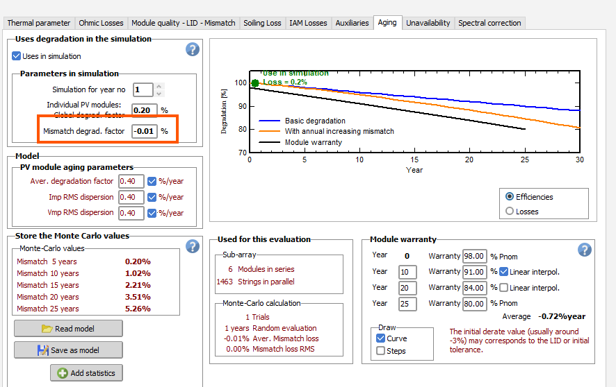
Hi @Sed Mir, thanks for reporting this issue. It turns out this happens because of a small interpolation error, which we had not noticed before. Usually the interval year 0 - year 5 has a smaller differential than year 5 - year 10. As a consequence, since we use cubic splines, there is oftentimes a small dip in the interpolation curve just after the first interpolation node (after year 0). Because the first operational year's loss is evaluated at 0.5 year, this happens to be within the dip, and turns out negative (though very small).
-
It's a pain in the neck to have to either create a new site or ask for the SIT file when you get a PVsyst export from someone else. Why isn't the SIT file included in the exported project zip file? It seems like a simple change and would make many users happy.
-
 Our team has observed that the DC and AC line losses we set can change when we work on a different parameter in the Ohmic losses tab. We set the loss in %, but PVsyst has this tendency to recompute the wire gauge (or something) when we adjust the transformer losses. If we use a number in percent, that's the number we want, not something recomputed for line length or expected current. As it stands, we have to look carefully every time we exit the Ohmic losses tab. Incidentally, I'm not aware of any PVsyst run I've been involved with (mine, IE's, consultant's) in my career where the user has entered wire gauge or distance to calculate the loss, only %, so it's important that we be able to trust our settings to remain fixed.
 -
Could we please have a way to set global default units for reports? I'm tired of having to reset them every time I start a new project -- or getting through several runs and realizing I need to go back and rerun the reports. Thanks. Incidentally, kWh is an impractical unit when working on utility-scale projects. The reports show the power output as nine characters without any delimiters -- almost impossible to read.
-

Decomposition and transposition models
Michele Oliosi replied to dina.christensen.martinsen's topic in Meteo data
Regarding the Perez-Driesse model: we are looking into it, especially for reverse transposition. I think it will be included at some point. However, while it does address the discontinuities, as far as we understand it does not remove biases when applied on sub-hourly data vs hourly data. -
Hi, There is a procedure to create the CLI folder in your workspace, even if I agree, it's not really intuitive: https://www.pvsyst.com/help-cli/use-cases/index.html#ready-made-pvsyst-cli-use-cases To access this folder, Click on Manage or File -> Workspace to open the workspace management window, then click on Reload templates to update the CLI folder content. You can find more details in PVsyst help A directory containing ready-made examples of PVsystCLI application is located in PVsyst Workspace in CLI\Ressources\examples I suggest doing this instead of using the source files directly to avoid potential issues with your installation.
-
Check in this folder: "C:\Program Files\PVsyst8.1.1\DataRO\PVsyst8.1_Data\CLI\Ressources"
-
Found it, in my case it's located in: "C:\Program Files\PVsyst8.1.1\DataRO\PVsyst8.1_Data\CLI\Ressources"
-
Hello, I can see in PVSYST CLI help (https://www.pvsyst.com/help-cli/reference/cli-command-generator.html) that there is an excel file which helps creating the commands to be used in CMD for PVSYST CLI. I think it's called "PVsystCLICmdGenerator.xlsx". The website says that it's located in "examples\PVsystCLICmdGenerator.xlsx" but I don't have that folder in my computer. From where can I download the file? Thanks and regards.
-
 Osura Danthanarayana joined the community
 -
 buypeptideso1122 joined the community
 - Earlier
-
Hi PVsyst Team, Has any progress been made with modeling the new technology modules?
-
Why first year mismatch degrad. factor is not zero? Why it has a negative -0.01% value?
-
 Myron joined the community
 -
 corepeptides9 joined the community
 -

Decomposition and transposition models
James Barry replied to dina.christensen.martinsen's topic in Meteo data
Thanks for the clarification. Indeed there is a large amount of literature on the topic. It would probably make sense to be able to use the same model for both time scales, or at least to provide this option. Another question - do you use the Perez-Driesse model [1] for the sub-hourly transposition, as discussed here: https://forum.pvsyst.com/topic/3644-continuous-perez-driesse-model/ . This model performs well for high resolution data and removes discontinuities in the modelled diffuse component. Without this improvement one can get discrete jumps in the results at minute time scales. It also performs well for reverse transposition. Driesse, A., Jensen, A. R., & Perez, R. (2024). A continuous form of the Perez diffuse sky model for forward and reverse transposition. Solar Energy, 267, 112093. https://doi.org/10.1016/j.solener.2023.112093 -
 Bhaskar solanki joined the community
 -
Trackers appear as "polygonal fields" -- problem using PVC scenes
LauraH replied to LauraH's topic in Problems / Bugs
For the same objects, I get the message "For 16 fields in the 3D scene, the orientation is not attributed." Not being sure whether these objects are being treated as trackers, I'm not inclined to spend the time trying to fix this, but this is an error, not a warning. Is there any way I can have PVsyst ignore this? I could just delete those objects. It's a big shading scene.