All Activity
- Today
-
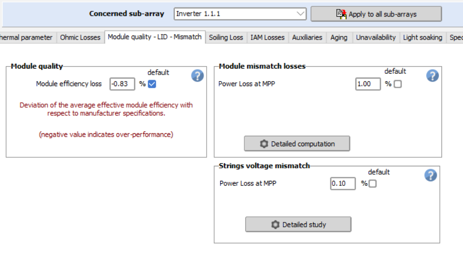
This depends on the PV module you have defined in your subarray. The LID box is only visible when the LID is pertinent, I.e. with crystalline modules: siMono, siPoly, HJT
-
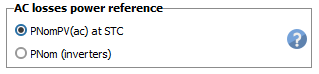
In the AC losses part, the reference power may be either the STC power of the PV array, or the PNomac output of the inveters. This choice is done in the project's settings: In this case the PNomac of the inverters is the nominal power (not the possible max. power at low temperature). NB: In your case the choice of the reference power is the array STC power (nameplate of the PV modules). However the reference power choice affects the ohmic loss parameter when expressed in terms of percentage. The basic definition of the ohmic losses is the cable Resistance. When operating, the ohmic loss is proportional to the square of the current. When expressed as percentage of the power it is proportional to the power. This is explained in detail the help https://www.pvsyst.com/help/project-design/array-and-system-losses/ohmic-losses/index.html. As an example: You have defined a MV lines loss of 1% for a PNom at STC = 8.2 MWp (PV array). Now if you have a PNomac(inv) of, say, 6 MW, the relative loss at PNom(inv) will be 1% * 6MW/8.2MW = 0.73%. You can check that if you change the referenc power in the project's settings, the relative losses will drop accodingly in this dialog.

-
Following the new PVsyst update we must specify the tilt angle we would like to modify parameters for on several different sections of PVsyst. I am concerned that this creates an opportunity for mistakes if each orientation is not modified as needed, and would also like to know why the individual orientation (tilt angle) modifications are necessary. For example, we are to add separate albedo values for each orientation, but how would we have different albedo values based on orientation within a single site? Is there a resource to better understand the new updates to orientation/ tilt so that I can ensure I am using them correctly? Kind regards.
-
 currentaircraft joined the community
 -

PVsyst Aging _ Clarification on Degradation Calculation in PVsyst
André Mermoud replied to Kanagavel K's topic in Simulations
This is explained in detail in the help https://www.pvsyst.com/help/project-design/array-and-system-losses/ageing-pv-modules-degradation/index.html?h=ageing The LID degradation occurs in the first hours of the system operation. It is simply treated as a diminution of the PV module efficiency, whatever the operating year. In your case it should be specified as null. This curve is a warranty for each individual module. It does not describe the average ageing behavior of the PV system. -
 Rodrigo Figueroa joined the community
 -
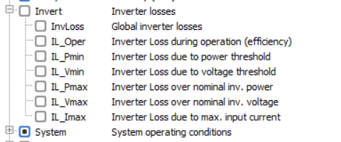
Hello, I am performing a simulation and has realised that LID box is not appearing when defining the detailed losses of the system. I attach a picture showing the issue. What is the reason it does not appear and how could I solve it? Thanks in advance. BR, Auxi
-
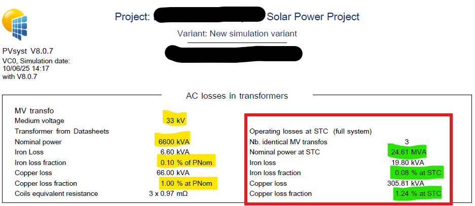
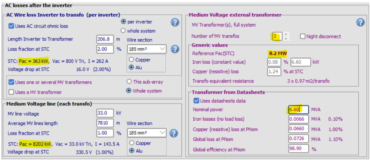
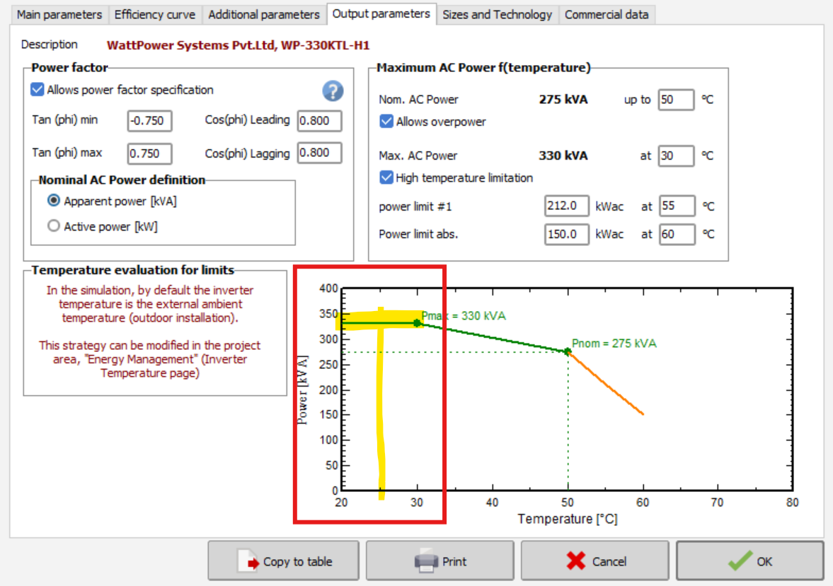
Dear PVsyst Team, I need some clarification on the AC Losses portion, 1) AC Transformer Losses portion While defining the losses from the datasheet tab (6600kVA Nom.Power) 3 Nos of Trafo is used in the project so total Nom.Power will be 19800kVA. here, the point to be noted is that no value of temperature is being defined in PVsyst. Then, how the Nominal power at STC calculation is performed in internal pvsyst (at transformer side). 2) AC Wire Loss Inverter to Transfo Inverter ratting Nominal power at 50deg is 275kVA and as per the power vs temp curve (image is attached here for the reference) 20 deg to 30deg the power is 330kVA only Then, how the Nominal power at STC calculation is performed in internal pvsyst (at inverter side).
-

PVsyst Aging _ Clarification on Degradation Calculation in PVsyst
Kanagavel K replied to Kanagavel K's topic in Simulations
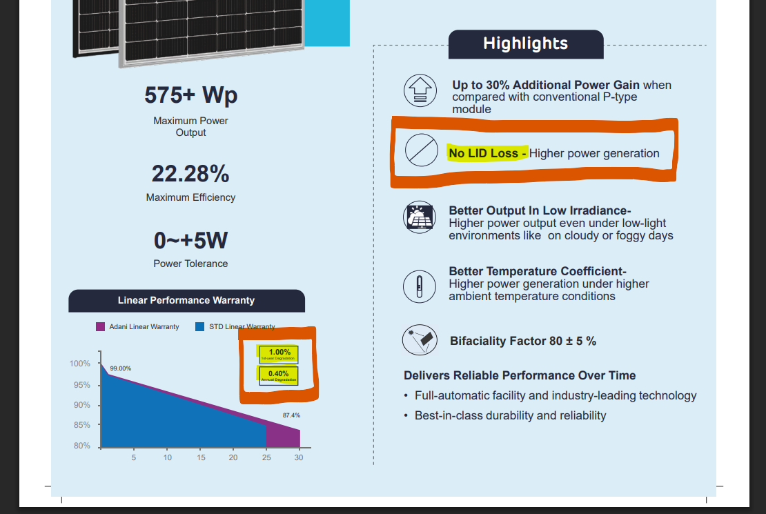
Dear PVsyst Team, I need one clarification on the LID and Aging parameter input. LID is "0", 1st year loss is "1.0%" and annual degradation is "0.4%" as i attached in the below datasheet for the reference in this case how should i defined the values in Pvsyst (LID, Aging). Thanks, Kanagavel K
-
 Hello, By importing irradiance data in the plane, PVsyst applies a reverse transposition to determine the global and diffuse horizontal irradiation required for the simulation. For the simulation, PVsyst will utilize the Global on horizontal plane as starting point. This is necessary as the optical treatment (shadings, IAM, etc) requires the beam, diffuse and albedo components. The reverse transposition and re-transposition can indeed cause some discrepancies with the original data. Verify that you in the Simulation use the Hay transposition. You define this is the project settings. You can read more about the transposition model in the following help pages: Transposition model - PVsyst documentation The Hay transposition model - PVsyst documentation
 -
 Sanjoy Pal joined the community
 - Yesterday
-
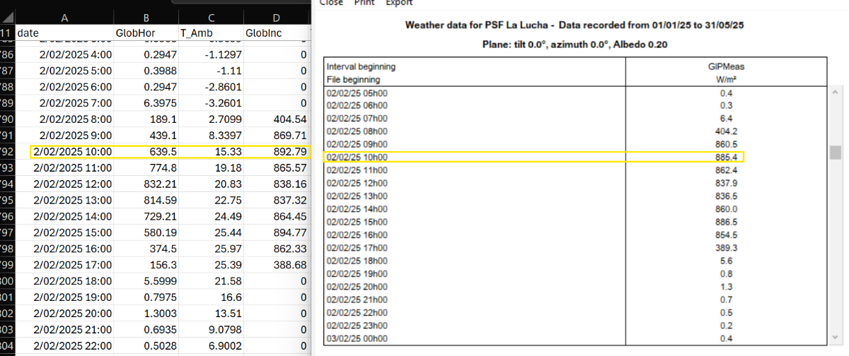
 Hi everyone, I've noticed something curious while working with a custom .MET file that includes field-measured irradiance in the plane of array (GIPMeas). After running a simulation and generating the 8760 output file, I've seen that the GlobInc values sometimes differ from the GIPMeas values input. I understand that GlobInc represents the global irradiance on the plane of the array, but I was expecting it to match the GIPMeas data directly, since that's what I used in the .MET file. I’m attaching a screenshot showing a comparison between GIPMeas and GlobInc for reference. Does anyone know why these differences occur? Is there some internal processing or adjustment done during simulation that could explain this? Thanks in advance!
-

Unexpected Behavior of the Automatic Altitude Toolmatic Altitude Tool
Alberto replied to Alberto's topic in Problems / Bugs
Just bumping this for visibility. I'm still looking for some help with this. Thanks in advance! -
I don't know what you have defined as Charging device power in the Grid storage dialog. Probably around 100 kW. Now I see that these hourly values correspond to a power of 1.4 kW, i.e. 1.4% of the nominal power. At this power level, the inverter efficiency profile (defined by a maximal and EURO efficiency) is very low, close to 0.
-
 Alvie joined the community
 -

Near Shading of Objects Bug - PVsyst 8
Eric Poirrier replied to Evan Westphal's topic in Problems / Bugs
Hi Vamsee, Unfortunately, the issue with PV Fields not receiving shadow when they are set as non-casting object is still present in the latest version of PVsyst. For the PV fields to receive Shadow the PV itself need to cast Shadow (Shadow casting ON). Can you set your PVs to cast shadow? Regards, Eric -
 Vahidbehzadi joined the community
 - Last week
-
 machlithium joined the community
 -
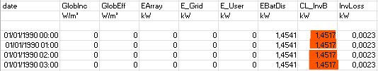
Hello, I made a simulation with Luna2000-200kWh (and a PV field of 100 kWc) with a self-consumption scenario. When there is no PV production and no User consumption, I see that the battery is in Discharging mode with a very high consumption of battery inverter : 1,4517 kW (CL_InvB) compared to the PV inverter consumption : 0,0023 kW See below the result file : How is calculated the CL_invB value ? Is it possible to parameter it ? Thank you
-
 JN GARDERET joined the community
 -
Hello, the map of the newly created site in version 8.0.12 is not available,8.0 Other versions do not have this problem
-
 SIMON joined the community
 -
 Matthew Kirby Bsc joined the community
 -
Inverter output power by .OND file
André Mermoud replied to Andrés Fernández's topic in PV Components
It uses the last two points. -

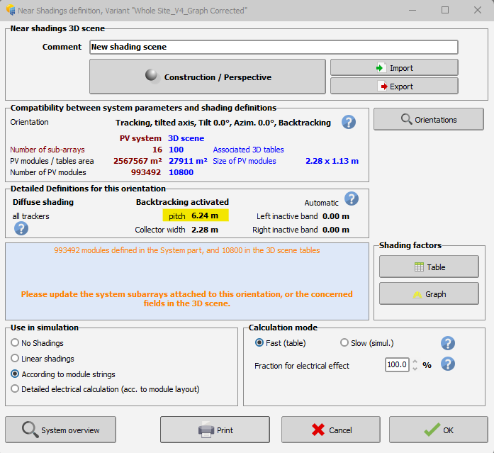
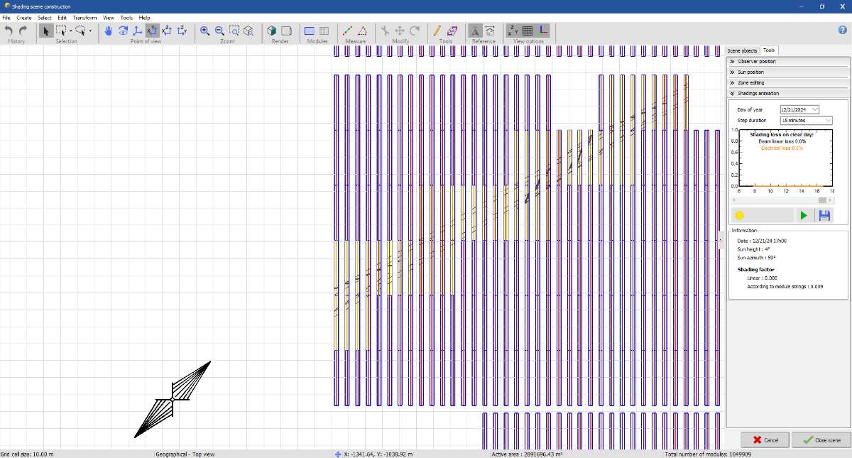
Pitch value set in shading scene not matching pitch in report
Michele Oliosi replied to Vera's topic in Shadings and tracking
PVsyst usually takes the minimum pitch as default value for the backtracking algorithm. If only one of your trackers has a pitch of 6.24 this may explain what you observe. Note that you can anyway override the backtracking parameters from the 3D scene > Tools menu > Backtracking management. -
Hello, I suggest that you run a simulation with the bifacial parameters and export an hourly output file with all the relevant parameters, such as overload losses etc. This can not be done for individual strings but for the full system. Running several iterations should give you a good estimate of the losses.
-
Hi Linda, Thanks for the response. The requirement arises in order to optimally size no. of strings to MPPT of central inverter while complying to maximum current limitation of MPPT. Since the rear side current in bifacial is highly variable parameter I wanted use PVsyst to get fair estimation of it so that MPPT can loaded optimally, avoiding clipping losses. Can you suggest some solution here? Also can we find the single string current from IArray with total no. of strings
-
 My PVsyst report is showing a pitch of 6.24 even though I have set the pitch to 6.25 in the Shading Scene. How can I fix this? Thank you, Vera
-
Is this resolved I am also facing the same issue. Object shadings are being considered and the adjacent tracker shading is not being considered. is there any work around.
-
Inverter output power by .OND file
Andrés Fernández replied to Andrés Fernández's topic in PV Components
Thank you for your response. Does the linear extrapolation you mention use all points or the last two points of the table? Regards, -
Hello, The most straightforward way to evaluate bifacial gain is to run two simulations: one with bifacial parameters activated and one without. While the current itself does not differ between the front and rear sides, the rear side does contribute to the overall energy production. In PVsyst, the results are presented for the entire system and not broken down per string.
-
Hello, PVsyst is calculating the sun position based on the exact year accounting for leap years, when specific years are simulated. Thus, if you import a specific year that is a leap year though the 29th is missing in the data set, it will be considered as missing data and values will be 0 (similar to as if any other date of the year was missing). So values for February 29th will be zero (e.g., no irradiance), but the date will still be included in the simulation. March 1st will correctly follow as the next day.
-
Hello, You can read about how to adapt you PVsyst simulation to a floating system in the following post: https://forum.pvsyst.com/topic/1346-how-to-adapt-pvsyst-to-floating-pv-systems/
-
Hello Tyler, Essentially, the Global incident in the collector plane will be calculated for each sub-array for the assigned orientation (or possibly a mixed orientation). The GlobInc as the total result is an weighted average based on the Pnom PV