lonav
-
Posts
13 -
Joined
-
Last visited
-
Pérez transposition model, PVsyst vs. satellite database
lonav replied to EA2EQD's topic in Meteo data
Hello André, When you say "the horizon shading is taken into account before applying the transposition" would that mean that, loading a horizon profile for the site is always needed to balance out this diffuse contribution on the GlobInc calculation so that, when comparing against GPOA measured onsite with in-plane pyranometers (Gmeas) and calculating performance there are comparable figures from theory (Egrid/GlobInc) to reality (Eactual/Gmeas)? This of course, under the ideal scenario when the same weather conditions and system performance would happen. I do not get to understand how this horizon shading is taken by PVsyst when no profile is loaded, since GlobInc result does not vary if there is one or no file from any source. Does it estimate it or calculate internarlly once the site coordinates are set by reading internal databases? Thank you. Regards. -
Hello, Any update on the topic? I am seeing the same issue with other inverters and sites. The programm is calculating around 1% more power 20 to 30 hours over the year. Could there be some default setting causing this? Thank you in advance for your help.
-
Dear PVsyst team, When running bifacial simulations I have noticed that module temperature remains the same as in the equivalent monofacial system, thus not taking into account extra heat from the rear side. Since Array thermal losses seem to be calculated with both front and rear incident irradiance effect, I was assuming so should module temperature. Could you please explain the reason for this? Thank you in advance.
-
Hi, I have been running some simulations with bifacial modules and it caughts my attention the fact that the performance ratio calculation does not take into account the global in-plane irradiation on the rear side of the module. Should not it be added to the calculation to comply with the PR definition? Thank you in advance for the help. Best,
-
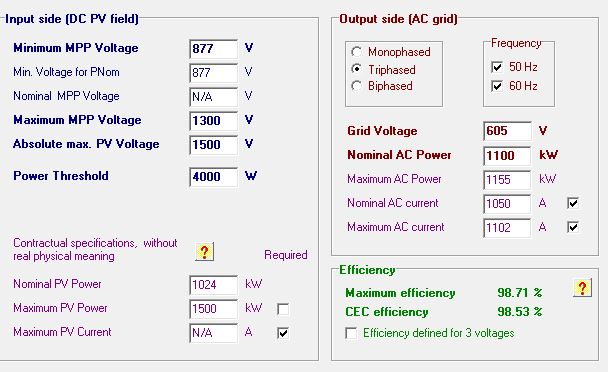
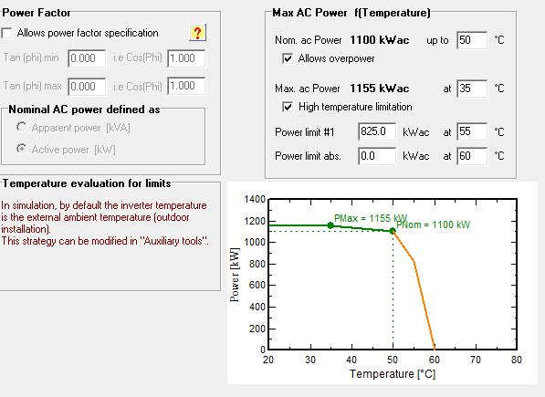
Hi, according to the OND, maximum power should be delivered at 35°C so there should be no chance for higher power at the inverter output. I have simulated a power block formed by 2 inverters as the one described before. When looking at EoutInv field on the hourly CSV export file from PVsyst I see the maximum value is 2339 kW, which will mean each inverter is producing ~1170 kW, when max. export power is 1155 kW.
-
Sorry, I didn't explain it the right way. It's not 15 kW in total; the software is giving 15 kW more per inverter (specification as per the jpg files attached before). What other explanation could there be for it? Regards,
-
Dear Andre, I have read the thread and I wonder if you came up with an explanation for this. In my case, for a 200 MW plant, I am seeing the inverter I am simulating with exceeds the specified max AC power by 15 kW around 20 hours. Could you help me clarify why this happens? Attached are two screenshots from the ond file so you can have enough information about my enquire. Thank you in advance for your help. Regards, Lola. Inverter OND specification_2 Inverter OND specification_1

-
Hello, I have a question which I think is related to this post. I have simulated the shading effect of a tracker screw bar at the worst case scenario (meaning the bar tilt which will cast the largest shade on the modules). The bar is not defined as a thin object though. Now, as for the shadow animation there will be some little shadings and I would expect that to be seen in the "E grid" values, but the outcome is the same as if there were no bars. Is this the consequence of the shading loss being so low (less than 1 W·h) that the program would neglect it? Thank you.
-
Hi, I am trying to find a way to customized OND files. Whenever I create one from a datasheet, I see that in "Output parameters" the derating values dissappear from one simulation to another. Also when simulating w/o self consumptions included in the file. This does not happen when the manufacturer provides the OND file. Now that component files are editable (with Notepad++ for example), I have created the file from a manufacturer's .ond text file. So far it seems it works but, could you confirm this is a safe way to avoid changes in the file configuration, please? Thank you in advance, Lola.
-
Thank you André, that was what I needed to know.
-
Hello, I've tried to check module efficiency in the balance for thermal loss U · (Tcell - Tamb) = Alpha · Ginc · (1 - Effic) (using U=Uc=29;alpha=0.9, as for panfile) by back-calculating from hourly Tarray values and I see the outcome is greater than the module efficiency most of the time. Am I missing something? Is this a relative efficiency perhaps? Relative to what? Thanks. Regards, Lola.
-
Hi André, as meteo data suppliers provide wind velocity measured at 10m high and wind data inputs for PVsyst standard format meteo file need to be values also at 10m, does the programm recalculate wind velocity for the height of the array (~2m for a free-mounted system, for example) in order to compute array thermal losses? In the help it mentions the Uc value of 29W/m²K has transferred the wind-dependent coefficient assuming average wind velocity of 1.5m/s, but is that value a 10m high measurement? Do I need to recalculate wind velocity if it's not measured at the height of my array? Thank you in advance for your help.
-
Dear sylvain, I just discovered this feature and once selected I have added objects to the green folder so they have turned dark blue, but what do I do next? Whether I run linear mode or according to strings the software will freeze when pressing the "Table" button just like it would do when simulating for a large tracking array and never ends de simulation. How do I need to proceed after creating my group for "partial shading calculaion"? Thank you.