SE2015
-
Posts
39 -
Joined
-
Last visited
Everything posted by SE2015
-
Hi, I have an existing multi orientation system that am trying to simulate in PVsyst. The pyranometer is installed parallel with the modules on one of the orientations. When I import the POA hourly data, PVsyst warns me that the data is only applicable to the modules belonging to that orientation. Will the simulation of the entire system be correct, or do multiple orientation systems require multiple pyranometers, if they are tilted? Thank you
-
Hi, the image below shows meteo data I am inserting in version 7 vs version 6.87. For some reason I get a kt error in V7. Any thoughts as to why? is there a hidden parameter I can change to fix it? Thanks!

-
The SolarEdge nominal Pnom ratio can be raised in the hidden parameters (parameter ID's 280 and 281). Don't forget to also raise the "Nominal Pnom Ratio" to the level you need in the Strings Configuration interface.
-
SolarEdge Optimizer - string power difference error
SE2015 replied to tranterengineering's topic in Problems / Bugs
Hi, You are correct. To allow for string oversizing, 3 strings must be connected to the inverter. -
As far as I know, the way to do this is to convert the DWG file to either *.3ds or *.dae, which can be imported into PVsyst.
-
Is it just me, or is the new site map (as of V6.77) slower and more importantly, does not allow a direct input of coordinates? A direct input of coordinates for the new SIT was very helpful (now we have to trawl the map to find the correct spot...)
-
Has the growth of mismatch been included as well, or just the aging? Thanks
-
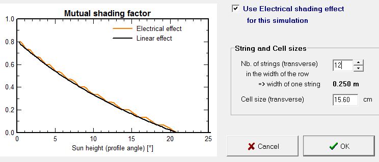
The "Nb. of strings (transverse)" refers to the number of modules you have stacked in one table. But, if you are using MLPE such as microinverters or power optimizers, you need to specify the number of sub-modules, not modules. So for example, if you have a table that is 4 modules high, in landscape, then you will usually specify "4" in the Nb of strings. But, for the same system using SolarEdge power optimizers, for instance, you will specify "12" (because there are 3 sub-strings per module).
-
Importing 3D model of building increases area in PVsyst
SE2015 replied to uche_94's topic in Shadings and tracking
What may solve this is to import in inches. I don't know if it will solve your issue though, because of the extreme size difference you describe. Also, maybe use 3ds instead of dae, if Rhino can export in that format. -
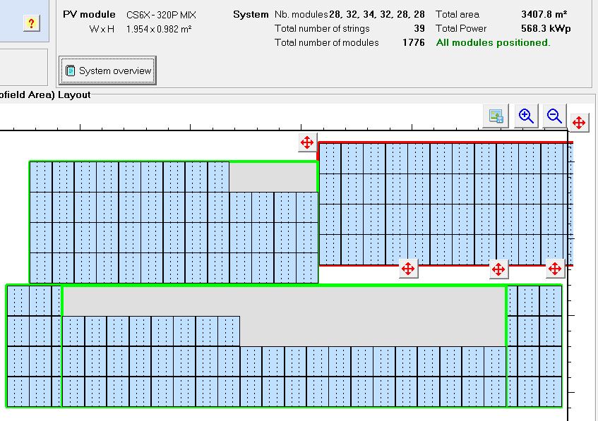
A current workaround I am using is to "snake" in an exclusion zone, like in the below image.
-
Does anyone know if the mismatch growth is included in the batch simulation? The module degradation is easy to show (even by using other params, as it is linear), but the mismatch growth will reduce production by an additional 2-3% over 20 years, needs to be included in the batch parameters list.
-
Correct, I see the warning now. I must say though that in V6.5x the functionality was better: we routinely use the module layout functions to verify our designs are correct (there is no other error-checking for this in PVsyst, other than manually counting the modules in the PV areas). We used to get a message like in the image below, telling us exactly where our discrepancy was. It's a shame to lose that functionality (now we only get a warning telling us we didn't do well, but not what we did...).
-
Hi, I notice that if my PV areas are bigger than the number of modules I designed, the Module Layout allows the simulation to proceed and does not warn of a discrepancy, as it used to do (it was a very useful error-checking tool). See the image, quite a few modules are missing from the scene, but the simulation can continue. i think this will have an effect on the shading response of the system. Thanks
-
Hi, in V6.61, when I partition the modules in a PV area into one string (i.e. the PV area will have a 1x1 sized partition), many times the PV area is deleted. Several 'undos' will bring it back, but I can't successfully proceed with the partition.
-
Hi Tecnum, When you select an object, then you click the red cross on the toolbar. You will see the three arrows allowing you to move the object. In order to edit an object, you select it and click the "wrench" button on the toolbar. Is that what you are referring to?
-
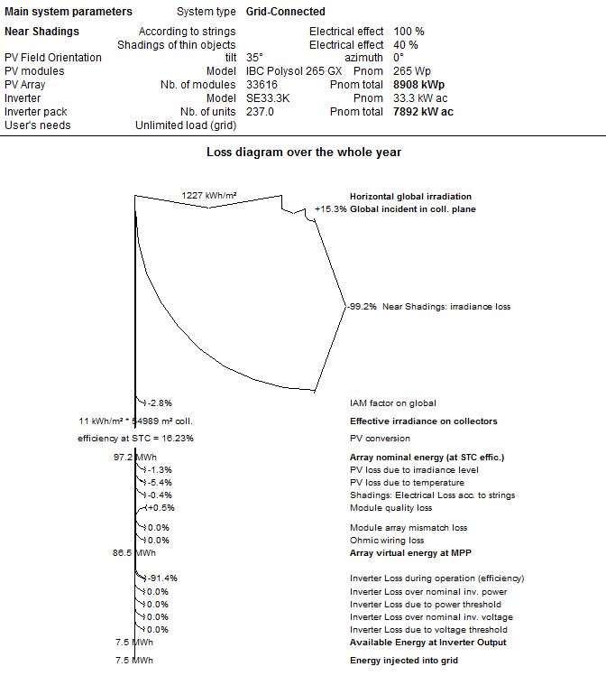
Hi, in V6.60, my shading table looks OK, but the irradiance loss seems a tad high :-)
-
This is indeed a great feature that will really help when designing large ground-mount arrays. Until PVsyst implements this feature, I found a work-around (not perfect, but when you have 10,000 modules, every little bit helps to save time). First, I use the image overlay to create a polygonal zone that follows the site-boundaries. Then I manually enter the dimensions and row-pitch of one PV module table (let's say a table of 4 strings stacked on top of each other - depends on your project). Then I ask PVsyst to populate the zone with these tables. If your angled border is on the right, you can specify that the population will start on the right side. This will give you automatically the angled site-boundary distribution. What's now left to do it "fix" the tables along the other end of the site, which will not conform to the design very well. Sometimes this really helps me save time.
-
This is a topic that has also been requested, recently, in a different thread. I reiterate the need for this feature. LCOE calculations rely on the lifetime production results, not just year 1.
-
I also agree, this would be very helpful for financial calculations. I hope it is a planned feature.
-
Hi, We are seeing a problem with module layout in V6.48. Portrait orientation produces unwanted results, see the attached images from the same project: Version 6.47, versus version 6.48. Version 6.47 Version 6.48 Thanks
-
I am also seeing this problem - in version 6.47 as well... See image.
-
Hi, I have a question regarding the IAM factor: the help files mention that during the simulation it is applied to the diffuse component and the albedo component separately. Can you explain the different application? The help files are a bit vague about it. Thanks
-
A current workaround to this limitation is to design shorter strings, just for the PVsyst simulation (in practice you will install with the over-sized strings). This will have no effect on the simulation. So for example: you want to design an SE27.6K inverter with 3 strings of 22 power optimizers (each optimizer connecting to 2 modules in series, so the result is 66 power optimizers = 132 modules). PVsyst perhaps limits the string length to 18 optimizers, so you could instead specify 6 strings of 11 power optimizers, giving you the same result (66 power optimizers/132 modules). Any mathematical combination will work, as long as you get the number of modules you want. See the attached image.
-
I guess the question we are having is how to change the scale of the image. Most likely we will always need to change the size of the image a bit after we import it. I am personally very confused by the X1 and X2 parameters.
-
So as far as the shading calculation goes, I figure I should partition rectangles corresponding to the size of 1 module? Can anyone think of a better way? I imagine that most shading that is not inter-row shading will 'disrupt' some cells in an affected module, thereby immediately tripping the bypass diode, and therefore bypassing the whole module. In cases where there is a ground-mount system with additional shading (like from trees or electrical poles) - then I am stuck. This is because if the system is installed well (i.e. the cells are perpendicular to the inter row shading), then I use "Linear" shading loss. BUT, as soon as a different shade is introduced on top of the inter-row shading... then "linear" should be supplanted by the 1-module-partition I describe above (only for those affected modules). So I haven't figured a good way of simulating this type of system yet. Any ideas are welcome :-)