Jéremie Bernier
-
Posts
62 -
Joined
-
Last visited
Everything posted by Jéremie Bernier
-
Hi. Please consider following pages that may help you in understanding how to match your design with the system layout: https://www.pvsyst.com/help/project-design/shadings/near-shadings-3d-construction/object-types/pv-fields.html https://www.pvsyst.com/help/project-design/orientations-in-v8/system-and-3D-attributions.html?h=definition
-
Hello, can you please confirm if you started by setting up the system part and you want now to design the scene with PV modules and shading objects? Or if it's the other way arround? That is, you have already your scene (either manually created or imported from a 3d file) and need guidance so as to define the system part? If you want, you can send the exported zip file of your project (Project / Export the project) and send it to support@pvsyst.com so we can have a look at it
-
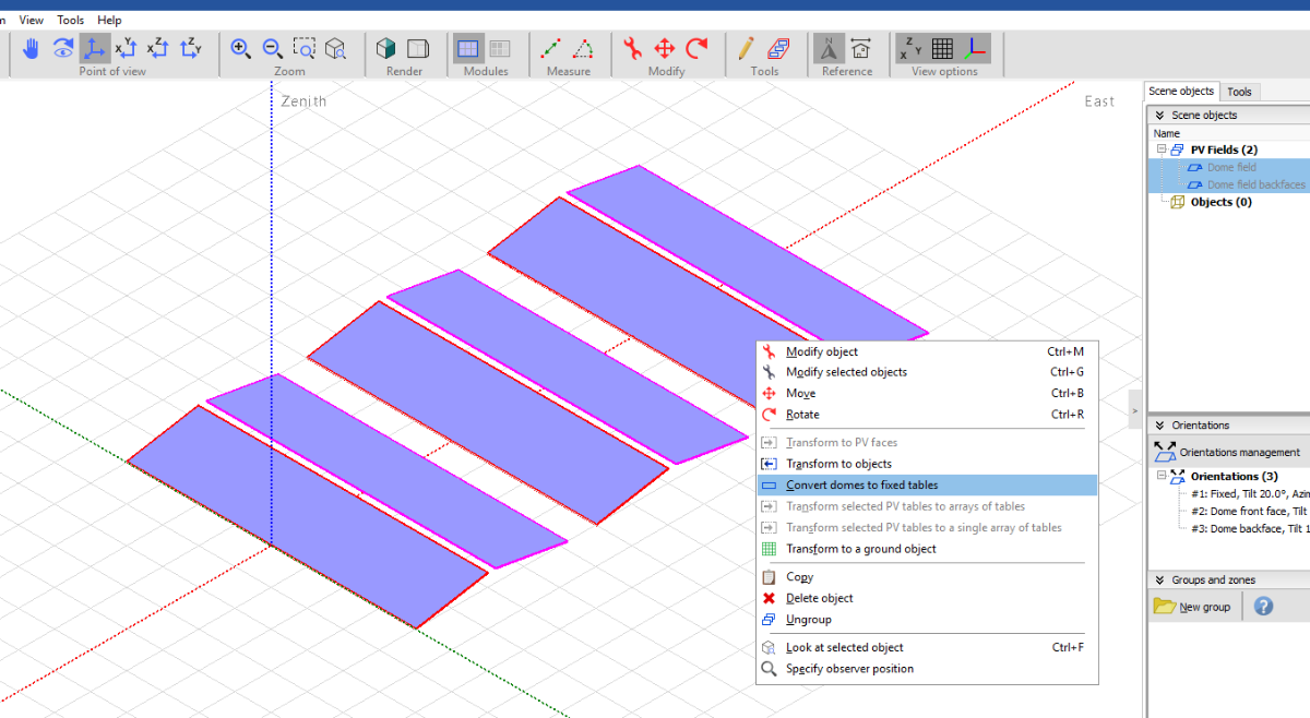
Hello Alexander, Since version 8.05 of PVsyst, you can convert your domes and array of domes to fixed tables. As a result, you will end up with 2 orientations matching your previous dome orientation. You can achieve this by right-clicking on your dome and select 'Convert domes to fixed tables' After this you will be able to link your last 'half dome' to the relevant orientation, and have your 2 orientations mixed together on an inverter (or not) in the system.

-
Hello. Did you use the automatic altitude feature? Right-click on the PV fields you want to adjust at the level of the ground and select 'Automatic altitude'. Does it fit on your ground?
-
 Hello NGD. The parameter is a positive value. The absolute value of the angles difference is checked against this parameter. My guess is that in the first case (15 - 12.6) you set a value that was sufficient to accept this difference, but not in the second case (109.9 - 93.6 = 16.3) Please check again Edit: Your error actually refer to parameter 'Tilt Spread Max'
 -
Hello. To better assist you with your issue, please send your V7 project to support@pvsyst.com
-
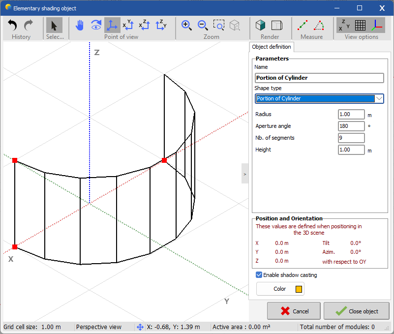
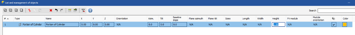
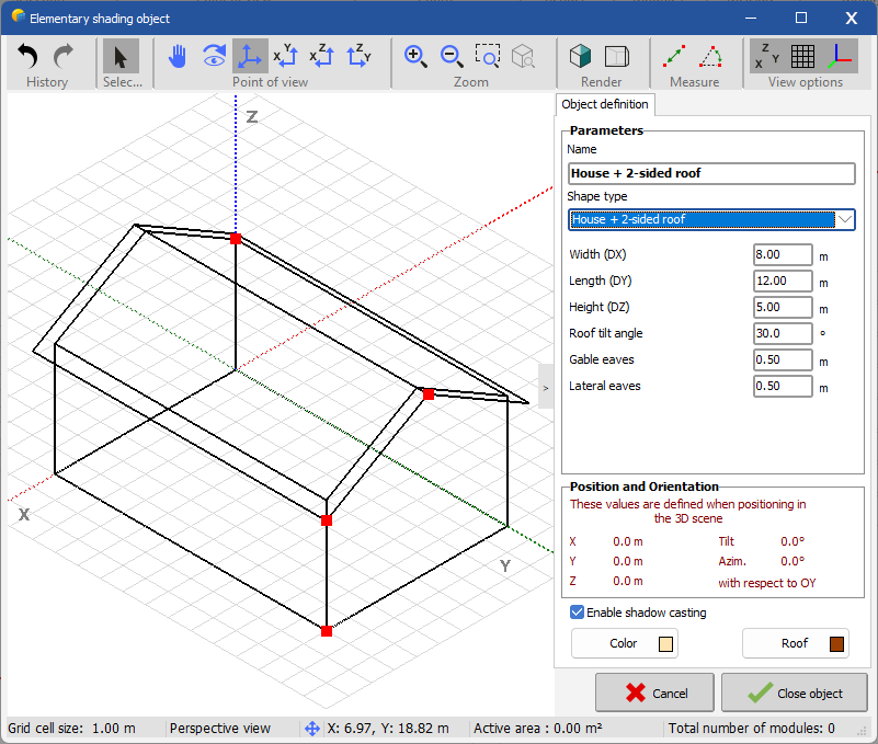
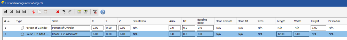
Hello. This is a 'Portion of Cylinder' The Height of this object is editable in 'List and management of objects' This object is 'House + 2-sided roof' It's height is NOT editable. So if you have already an object in the list thas editable height (like the portion of cylinder), the height for this object will be visible but 'N/A' As for the reason why height for 'House + 2-sided roof' is not editable, I'm not sure if it's by design or if it can be changed to editable. I will inquire and will request enhancement if it's possible. Regards
-
Hello, some object fields apply only to certain types of objects. In this case, if you have objects of different types you may have a non editable N/A value for a given object. For instance, heigh for object house is not editable in this tool, hence the N/A. It is editable for 'Portion of cylinder', and this is why the column is present.
-
Problem Unlimited Trackers 2D Model 2# Orientation.
Jéremie Bernier replied to rock_fire07's topic in Problems / Bugs
Hello. When you change a parameter value, just click in another field so the new value is taken into account right away. Also, I did the test - changed the Heigh above ground value - and it's been reflected after a few fractions of second in the graph. Please try again. Do you observe same behavior with other parameter - for example Pitch? -
angle between field and orientation is too high
Jéremie Bernier replied to Bilal Ahmed's topic in Shadings and tracking
Hello, this question is already answered on multiple topics in this forum. Consider for example this one: Regards -
3d tracker simulation uneven ground
Jéremie Bernier replied to Daniela Silva's topic in Shadings and tracking
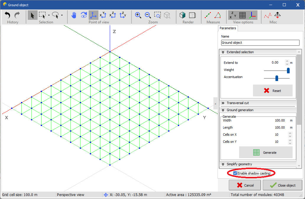
Hello, if you have a ground in your scene, edit it and make sure the box 'Enable shadow casting' is checked
-
No tracking orientation in Near Shading
Jéremie Bernier replied to Marija Ch.'s topic in Problems / Bugs
Hello Marija, You cannot directly select a tracker orientation in the Field Properties of a zone you're creating in the Zone Editing tool. Instead, you have two options: Option 1: Create your zone with fixed tables. Either select an existing fixed orientation or create a new one. Afterward, select these fixed tables, and convert them to trackers using the menu option Transform > Convert fixed tables to trackers. Option 2: Check the box for "Create tracking fields" in the Zone Editing tool. Even though the template orientation displayed in the tool remains of type Fixed, the actual orientation of the created fields in the 3D scene will be of type Tracking. Following either of the above methods should solve your problem. If the issue persists or you need further clarification, feel free to reach out. Best regards, -
Hello, there is no such limitation in the fields zone creation tool. If you encounter any issue, don't hesitate to send the export of your project to support@pvsyst.com along with an explanation of what you're trying to achieve. Regards
-
Hello, please refer to this other topic:
-
Hello, We have fixed issues that seem very similar to what you’re describing, and the update addressing these will be released shortly. However, to ensure your specific case is covered, please try saving your project just before the crash happens and send it to us (support@pvsyst.com). This will allow us to verify if the issue is already resolved or if it’s another unique case. We apologize for the inconvenience and look forward to helping you move forward with your project. Best regards,
-
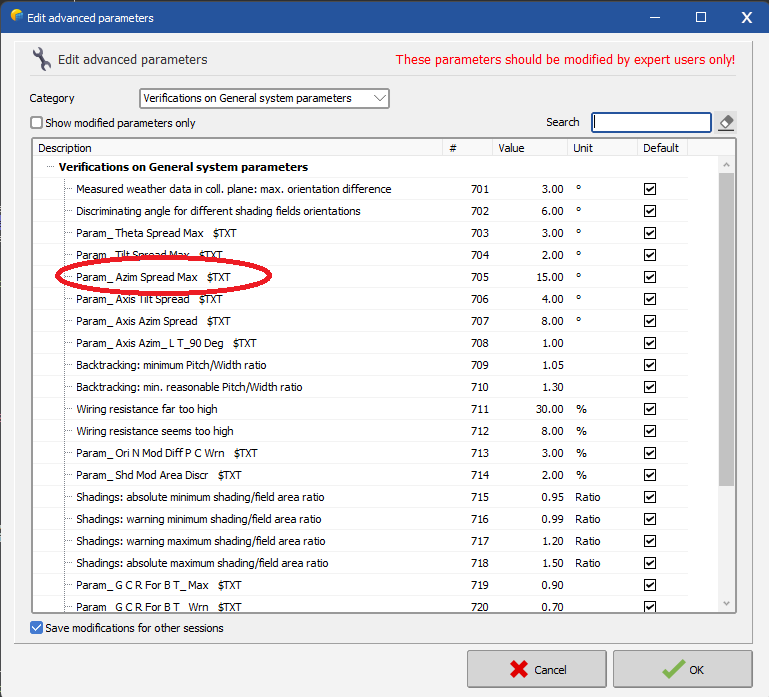
Hello, the parameter you're looking for is Param_Azim Spread Max. You can find it in the category 'Verifications on General system parameters'
-
Please check this topic:
-
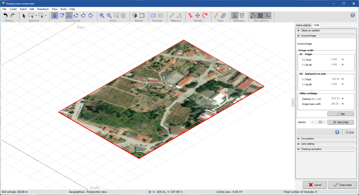
Hello, the crop button is available in the 'Ground Image' tool. You can right click on 'Ground Image' in the Scene objects and select 'Modify object'. 'Crop' button is at the right bottom of the tool as shown in the following screenshot
-
Terrain Mesh of PVC file uploaded to PVsyst is above the trackers
Jéremie Bernier replied to Aidenn's topic in How-to
Hello, I'm not sure which settings you're referring to. You can adjust the altitude of your trackers, but please note that there is no precise way to measure the altitude of a tracker from the ground if the terrain is uneven. If you're experiencing a specific issue with a PVC scene that doesn't render properly after being imported, please send the file to support@pvsyst.com, and we'll be happy to assist you. -
Terrain Mesh of PVC file uploaded to PVsyst is above the trackers
Jéremie Bernier replied to Aidenn's topic in How-to
Hello. Yes, you can use the Auto altitude feature on your trackers. If the terrain is uneven and there are significant altitude variations along the length of the trackers, you may need to increase the 'Distance to ground' value to prevent the issue of some trackers appearing below the terrain mesh. -
Bifacial Tracker - Backtracking - Zone -3D Nearshading
Jéremie Bernier replied to Aidenn's topic in How-to
Hello, Based on your description, it seems that the resolution of the ground data in your CSV file might not be sufficient, which could result in gaps or "holes" in the definition, causing some trackers to appear below the ground. To better understand and resolve this, could you please send us the CSV file you used so we can investigate further? You can send it to support@pvsyst.com, and we’ll take a closer look. -
Hello. To better assist you, please send your PVsyst project with the imported PVcase scene to support@pvsyst.com, and we will be happy to provide further guidance.
-
Hello, the help link i gave you states that the following file format are supported for import in PVSyst: - DAE : The Collada file format can be exported from many CAD software as it is an open format. It is available as an export format in Sketchup free version. - 3DS : Less used but still an export option in many tools - PVC : PV Collada file, open-source format derived from DAE format to include data about the PV modules and tables
-
Hello. Thank you for your question. Could you please clarify which specific tool or feature you are referring to when you mention "Auto Distribution"? Are you asking about the zone editing tool, which distributes PV tables in a defined area, or are you referring to automatic altitude adjustments to align the tables with the terrain?
-
Hello, to better assist you with your issue please send the export of your project in zip format to our support : support@pvsyst.com Regards