
.png.5a0f08430bae173944a56977dd41765f.png)

Muhammed Sarikaya
-
Posts
191 -
Joined
-
Last visited
Posts posted by Muhammed Sarikaya
-
-
Dear James,
Could you please share a screenshot of your system? It's unclear why some modules are missing.
Regards,
Muhammed Sarikaya
-
Dear Irakli,
First of all, don't modify OND file and PAN file.
Your problem is divided in two categories:
1. How to size a PV system with MPPT definition2. Limits and conditions for sizing a PV system
When defining your project, be careful to deactivate the 'MPPT feature' checkbox if you don't plan to configure it. This doesn't mean the software won't calculate based on the maximum power of the PV array.

The message 'The array Voc at -10°C is greater than the inverter's absolute maximum input voltage' indicates a major condition that must be respected when defining the PV system. You need to know that the PV array voltage changes with temperature, and if the voltage exceeds the inverter's maximum input voltage on a cold day, it could damage the inverters.
You can read more on this help page: https://www.pvsyst.com/help/systemgrid_vocond.htm
Regards,
-
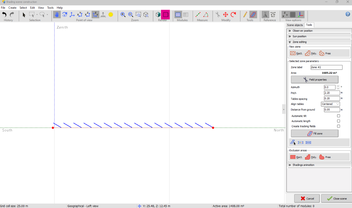
Dear Swonno,
You can click on these three buttons "X-Y" or "X-Z" or "Z-Y" to displayone side.
As a reminder, near shading it not intended for complex drawings. Try to keep it simple, as the purpose is to simulate the shading of objects on your PV plant.
Regards,
Muhammed Sarikaya
-
Dear Irakli,
In this case, don't use the topography in PVsyst if you plan to adjust all the supports to have the exact same tilt and azimuth.
Regards,
Muhammed Sarikaya
-
Dear Irakli,
Indeed, these values cannot be edited. When working on a project with complex topography in PVsyst, the solar tables installed in the field will often have actual azimuth and tilt values that differ from the expected nominal values. This occurs because the software automatically adjusts each table to the local topography, resulting in natural variations in these angles.
Can you confirm that you are working with a topography? Also, could you explain why you want to modify these values?
Regards,
Muhammed Sarikaya
-
Dear Irakli,
It's possible to change these values. If you select all the tables, your modification will apply to all the selected tables.
To modify the tilt, for example, just click in the box where you want to change the value, and it will be applied.
Regards,
Muhammed Sarikaya
-
Dear Claire,
It seems your view is in 'perspective view'; maybe you should try clicking on the 'Orthogonal Projection' button, and you will see your table at the same height.
Regards,
Muhammed Sarikaya
-
Dear Nikoloz,
Thank you very much for your suggestion. I will inform our development team about this feature.
Regards,
Muhammed Sarikaya
-
Dear Sarah,
In the previous project description, it seems that the PV array consists of fixed-tilt PV tables initially oriented towards the east and west. Due to the topography, the orientation of all tables will change, which is why it results in eight orientations.
What you mentioned about the horizontal N-S axis is used for tracking systems.
Tracking, horizontal N-S axis: this is the usual configuration of horizontal axis tracking systems.
Is this clear enough for you? Please don't hesitate to write to us."
Regards,
Muhammed Sarikaya
-
Dear Sarah,
I invite you to watch this video to understand how you can import a 3D scene into PVsyst.
I don't understand your second question. Could you elaborate and explain what you need clarification on?
Regards,
Muhammed Sarikaya
-
Dear Edwin,
I can suggest you to read this post:
The LID effect only arises with conventional p-type boron-doped wafers. Unconventional technologies using n-type doped wafers (as for example SunPower mono-facial cells) are not affected.
LID is a loss of performances arising in the very first hours of exposition to the sun, with Crystalline modules. It may namely affect the real performance with respect to the final factory flash tests data delivered by some PV module providers.
This loss is permanent over the entire lifespan of the PV module.
Regards,
Muhammed Sarikaya
-
Dear Irakli,
When running in DEMO mode (after the license has expired), you can operate the program and explore all options.
You can open existing project files (especially the DEMO projects), view parameter definitions and results, but you cannot save any files.
You will only have access to a restricted set of components in the database.
If you created a project during the trial license period, you can save your project and continue using it after you purchase the license.
Regards,
Muhammed Sarikaya
-
Dear Claire,
Is it possible for you to send us your project as a zip file to support@pvsyst.com?
I need to investigate and understand what the problem is?
Regards,
Muhammed Sarikaya
-
Dear Claire,
In 'orientation,' the method you use to define the position of the PV module will impact the 'global incident in coll. plane.'
You probably defined the orientation with a 0° tilt, which is why you are seeing a 0% percentage. Could you please check the orientation and let us know?
Regards,
Muhammed Sarikaya
-
Dear Alberto Cerrone,
Are you using multiple sub-arrays?
I encourage you to read this help page:
https://www.pvsyst.com/help/multi-mppt_more-examples.htm
Regards,
Muhammed Sarikaya
-
Dear Shivam Pandey,
It depends on you. How did you import or create the horizon line?
If you imported it from Meteonorm or PVGIS, the horizon is reliable, and you can use it for your simulation.
Regards,
Muhammed Sarikaya
-
Dear Irakli,
PVsyst is not responsible for the actions of its users, and we do not verify whether the results are accurate. We can only investigate in the event of a bug to determine its cause.
Additionally, I should mention that the azimuth in your projects appears to be incorrect. Please be aware that an azimuth of 0 in PVsyst corresponds to the direction of the sun.
Regards,
Muhammed Sarikaya
-
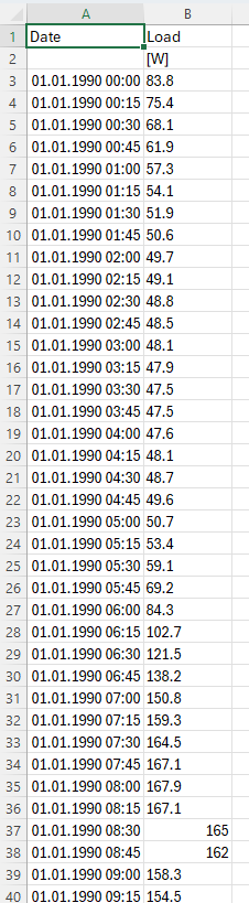
Dear MEURVILLE,
You must folow this model :
You must use the names 'Date,' 'Load,' and '[W]' at the top of the cells so that PVsyst can accept this load profile.
Regards,
Muhammed Sarikaya
-
Dear Panagiota,
You can only define losses for MV (medium voltage) transformers and HV (high voltage) transformers.
Regards,
Muhammed Sarikaya
-
Dear Giulio,
Unfortenately, we can't see results for every single inverter or subarray.
Regards,
Muhammed Sarikaya
-
Dear Sir,
We update the database using the requests of the manufacturers, and publish it with each new issue of PVsyst.
We can't of course follow all the new products of all manufacturers in the world. We don't want to include data without the acknowledgement of the manufacturer.
Nevertheless you can easily create your own components by yourself.
The easiest way is to choose a similar existing device in the database, modify its parameters according to the manufacturer's datasheets, and save it under a new name, therefore creating a new file in your database.
You have a tutorial for that on youtube: https://www.youtube.com/c/PVsystTutos, page Component database
Additionally, I invite you to read this page on how to determine IAM values
And how to establish pan file:
Regards,
Muhammed Sarikaya
-
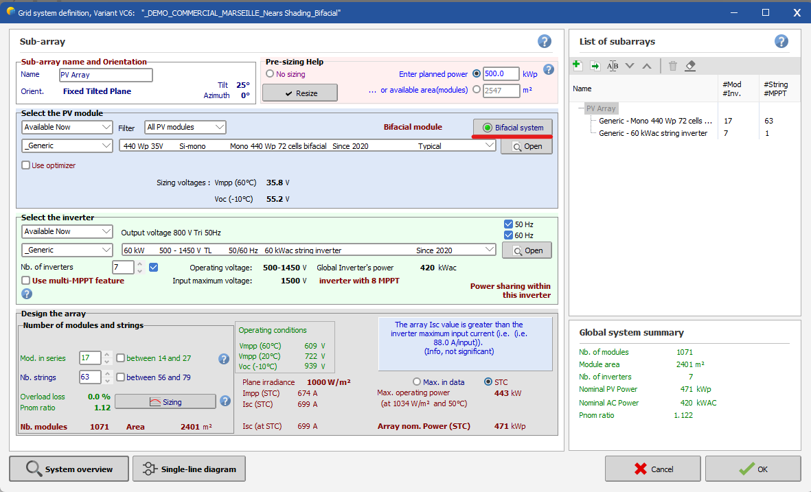
Dear Vera,
In your print screen, the bifacial module is not active as the green LED is not illuminated.
Here is an example of the bifacial module in use:
Regards,
-
Dear Rohit Rana,
Could you please send your project to our support email: support@pvsyst.com?
We need to investigate why you are experiencing this issue.
Regars,
-
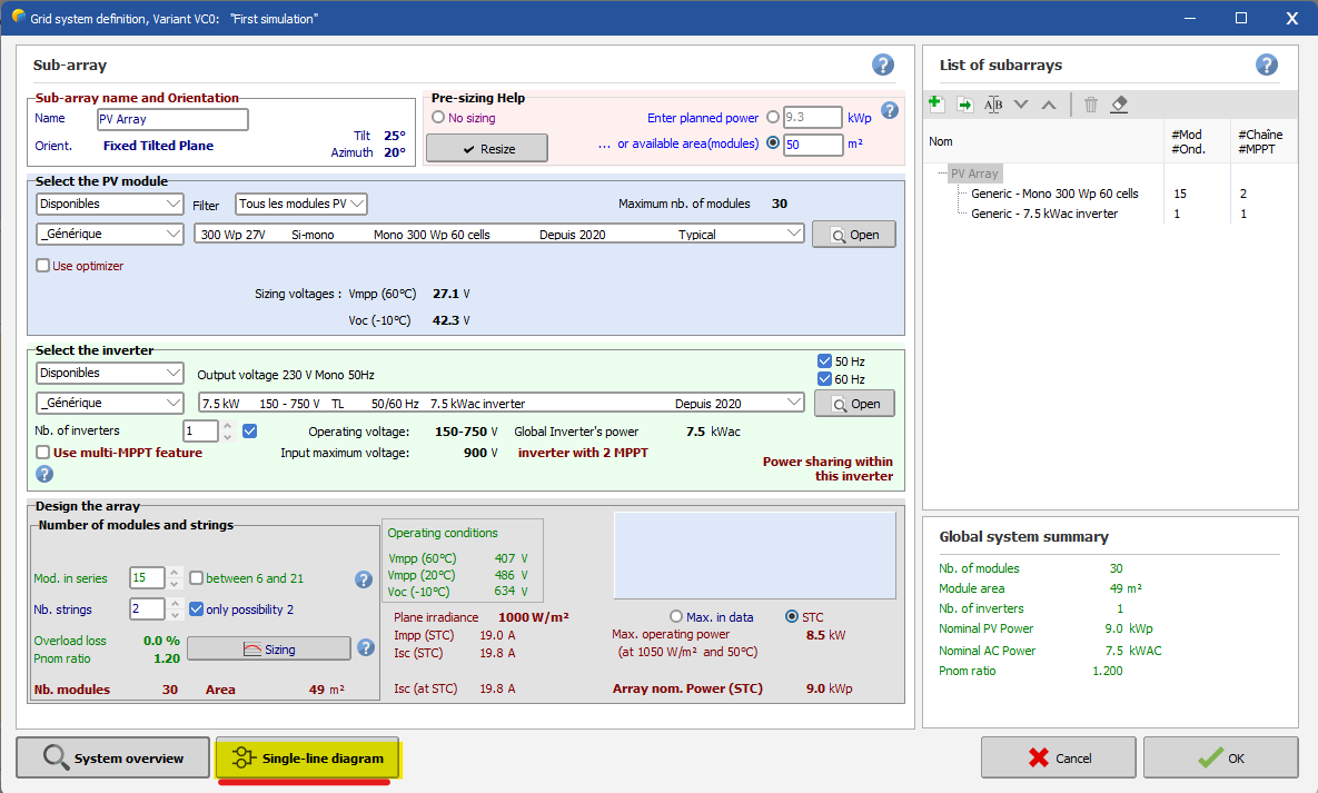
Dear Estagiario,
In the 'System' window, there is a button labeled 'Single-Line Diagram' below. You can click on it to visualize.
Regards,
Muhammed Sarikaya


Defining PV tables in 3D scene which with unequal number of modules on each row
in How-to
Posted
Dear James,
Can you explain your procedure for creating this table so I can understand what went wrong?
Regards,
Muhammed Sarikaya