-
Posts
211 -
Joined
-
Last visited
Posts posted by Muhammed Sarikaya
-
-
Dear Nikoloz,
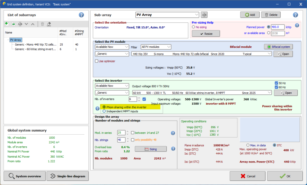
It seems that the inverter you want to use is a central inverter with only one MPPT. This means all strings connected to it must be identical.
So, you don’t need to worry about the MPPT definition. In PVsyst, just select the configuration “PNom sharing within the inverter” (see below).
Then, you only need to specify the number of inverters.
Regards, -
Dear Ishan,
First of all, the Unlimited Tracker represents an idealized PV table layout, with all rows having exactly the same length. Most likely, your 3D scene doesn't follow this idealized representation.
Could you please send us your project by email at support@pvsyst.com, so I can check it and explain why you're seeing these differences?Regards,
-
Dear Oli,
Unbalanced inverters are not designed for power sharing.
Regards,
-
Dear Arisk,
Unfortenately, this is not possible.
Regards,
-
Dear Ville,
Unfortunately, with a central inverter in PVsyst, it's not possible to perform what you want to do. You can try to modify the OND file by allowing multiple MPPTs, but this will not reflect reality.
Regards,
-
Dear Edwin,
Thank you very much for your feedback and for taking the time to report this bug.
Could you tell me how this situation occurred in your case, where the Medium Voltage panel remains visible even though you selected HV transformers? I need to reproduce this bug on my side in order to fix it.Regards,
-
Dear,
I can’t help you with AutoCAD or how to convert the topography to a CSV file. Maybe just make sure to check the X, Y, Z coordinates in the CSV.
With version 8, we can import topography from the internet — it might also be useful for you.
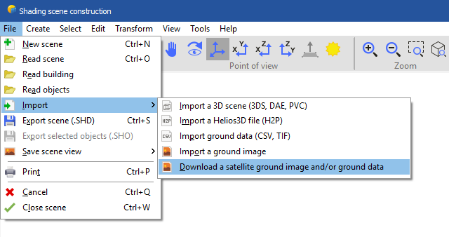
Here’s how to do it:
In Near Shading, click File > Import > Download a satellite ground image and/or ground data

Then, don’t forget to check “Also import topography data”
Regards,
-
Dear Cleyson,
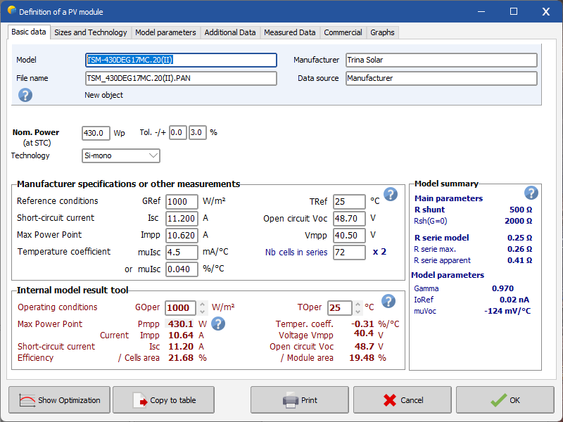
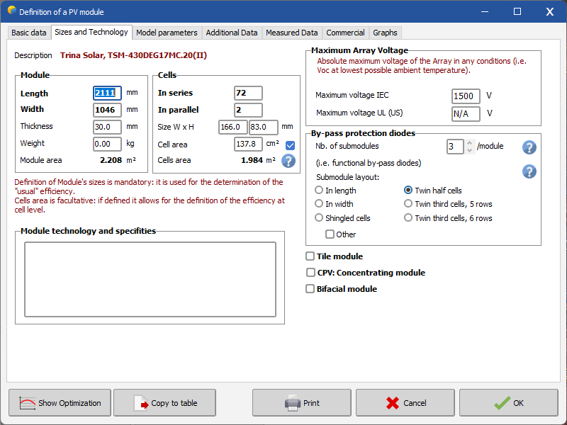
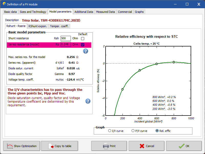
I created the PAN file based on the datasheet and didn’t get any error messages, see below:


Click on the "Model parameters" tab and select the default value for series resistance, as shown below:

Try using exactly the same settings and let me know if anything changes for you.
Regards,
-
Dear,
We update the database using the requests of the manufacturers, and publish it with each new issue of PVsyst.
We can't of course follow all the new products of all manufacturers in the world.
Therefore, please ask your provider/manufacturer to take contact with us for updating the database.
Nevertheless you can easily create your own components by yourself. The easiest way is to choose a similar existing device in the database, modify its parameters according to the manufacturer's datasheets, and save it under a new name, therefore creating a new file in your database.
You have a tutorial for that on youtube:
Regards,
-
Dear Terence,
Is it possible to send us the DAE file to "support@pvsyst.com" so we can also try it and check why there's a difference between the near shading and the report?
Regards
-
Dear Andrés,
I suggest grouping your PV array based on the electrical layout you have planned with the inverters.
It can add complexity to your project, so if you have a varying base slope, it's better to use a single orientation. PVsyst has implemented a new tool to estimate the percentage of losses due to slope variation.
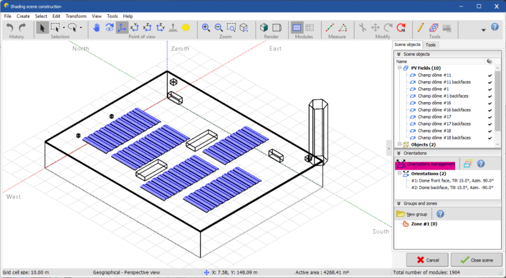
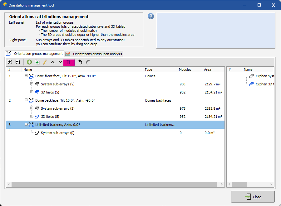
Go to the Near Shadings > "Orientation Management", then click on the "Orientation Distribution Analysis" tab. Choose the plot type "Base slope deviation, absolute errors". In my example below, you can see a loss of -0.02% due to averaging the base slope into one orientation:
-
Dear Swonno,
Can you explain what "origin feature in 3D scene" means?
Also, could you share how you placed your PV tables and what type of tables you are using?
In PVsyst, under Tools, there is an automatic altitude feature, but it works well only if all the tables are independent from each other.
Regards,
-
Dear Johnny,
First of all, in a self-consumption + storage system, the system responds to the user's load. So, if you have a small load profile and a large PV system, excess energy will be injected into the grid.
Since I don’t know your exact goal, I suggest creating multiple variants — starting with fewer PV modules, then trying with higher storage capacity. This will give you different results and help you find the best configuration.
Regards,
-
Dear Stewart,
In the Near Shading tool, you need to draw your 3D scene manually — it is not generated automatically.
I suggest watching our tutorial related to near shadings:
Regards
-
-
-
Dear Nikoloz,
You have to find a way to extract the three coordinate points (X, Y, and Z) of your 3D object and save them as a CSV file. This way, PVsyst will accept the CSV file as topography.
Regards,
-
Dear Laura,
Thank you for reaching out to us.
First of all, we will replace "Ageing" with "Aging."
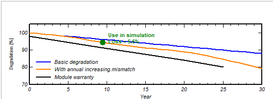
Regarding the manufacturer's lower limit guarantee, you can see it clearly in the graph below:

The sentence states that the module warranty represents the lower limit in reference to this graph, where it shows the loss of efficiency. It compares the black curve, which represents the module warranty, with the calculated aging curve, showing that the warranty curve has a higher efficiency loss than the calculated degradation.
Therefore, the sentence in the help documentation is correct in relation to this graph.
Regards,
-
Dear Emily,
I don't understand what you mean by "how can I assign specific modules from the 3D model to these two orientations."
I also don't understand how you can have 3,480 strings in one orientation and 699 strings in the other when you have defined a total of 35 strings. You must distribute the 35 strings between the two orientations.
I don't know how you defined the 3D scene, but you need to check which modules correspond to which orientation. PVsyst will automatically assign the number of modules based on the orientations you have defined.
Regards,
-
Dear Bommu,
Please send us an email to support regarding this project.
Regards,
-
Dear NGS,
Could you please send your project by email to support@pvsyst.com and explain what you are trying to do?
Regards,
-
Dear,
Indeed, both of your options provide good results.
Thank you for the advice. I will take note of it in our roadmap.
Regards,
-
Dear Alejandro,
Unfortunately, what you are trying to do is not possible.
Maybe you can approximate it by having the last two strings with the same number of modules in series.
Regards,
-
Dear Alejandro,
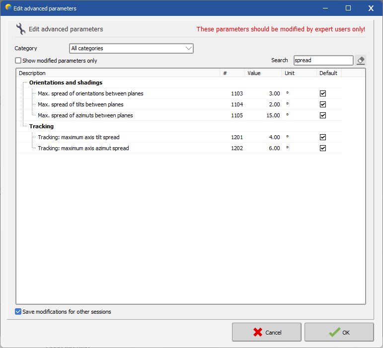
In the advanced parameters, you need to type "spread" in the search bar. See below:

You can modify these parameters and increase their values.
Regards,

.png.5a0f08430bae173944a56977dd41765f.png)


Midday spike in shading loss
in Shadings and tracking
Posted
Dear Alex,
Is it possible for you to send us your project at support@pvsyst.com so we can test it and compare the results between V7 and V8?
In your email, could you also explain the procedure you followed that led to these differences?
Regards,