jonipa
-
Posts
30 -
Joined
-
Last visited
Everything posted by jonipa
-
@Michele Oliosi would you please be able to comment on this? Thanks
-
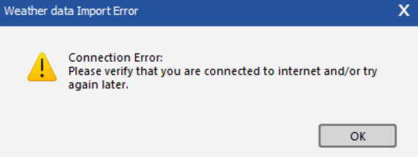
Hi, I am getting the following error while trying to get PVGIS TMY data from the weather data import: Anyone with the same problem? Thanks.

-
@Michele Oliosi @André Mermoud your help is appreciated. Thank you.
-
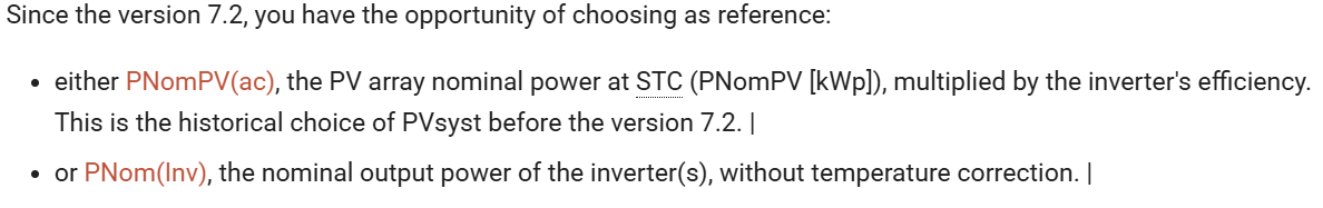
When defining the loss fraction, PVSyst mentions in the documentation: And when going to the definition of PNom of the inverter: When it says "without temperature correction", does this mean the ohmnic loss fraction to input at PNom(Inv) should be calculated at its maximum power instead of at its nominal power? As an example, it would mean calculating the ohmnic loss at 320kW (Pnom of inverter at 40ºC) or 352kW (Pmax of inverter that happens at 30ºC).
-
Hello, has this already been implemented in PVSyst 8? If so, how can we check the associated inverter derating loss due to high Vdc (Vmpp)?
-
How is the GlobInc parameter calculated in theses cases of large tilt spread? Is it the incident radiation on the average tilt plane? Is the average tilt plane calculated as a weighted average?
-
Shading losses applied after calculation of GPOA
jonipa replied to jonipa's topic in Problems / Bugs
Hello, no comments on this anyone? -
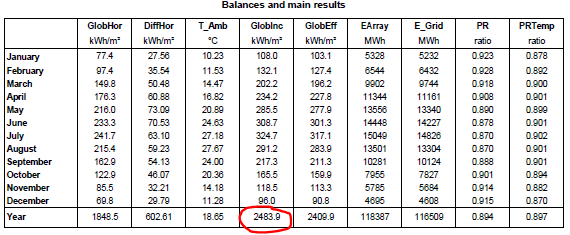
Hello, Taking a look to the project simulation losses graph and main results with which the PR is calculated some questions arise regarding GlobInc parameter. While in the main resutls table I get a yearly value of 2483,9 kWh/m2. The losses graph shows a value of 1849+34.4%=2485 kWh/m2. I understand it could be assumed as the same value though it is not exact. But the main question involves the next losses on the graph such as far and near shadings, reflection, diffuse, etc. They are applied AFTER defining GlobInc value but in reality (on-site) what we will be measuring as GlobInc will be a value in which shading losses, reflection, diffuse irradiance, etc. are already applied. To my understanding this has a big effect on the Performance Ratio value given by PVSyst as, in my opinion, the value of radiation used in the PR formula should be closer to the "Effective irradiation on collectors" value rather than "Global incident in coll. plane". Could anyone share their thoughts on this? Thank you!
-
I would also like to follow up this topic. It is still not implemented in PVSyst and can lead to errors on yield results, specially in high oversized DC generators.
-
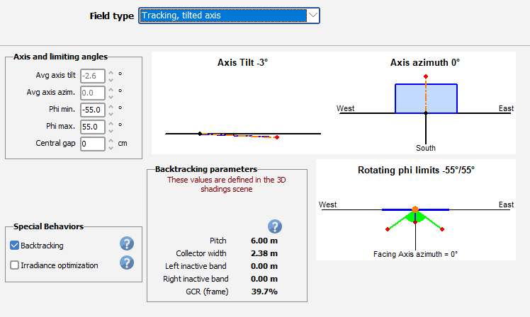
Had to set it to horizontal N-S tracker and just run the simulation without computing the shading table before. The shading table was computed while simulating and could get the results report. But after closing the results window the error pops up again.
-
Also tried so but when modifying PVSyst needs to recompute the shading factor table. Then "field type" changes to "Tracking, tilted axis automatically" again. Still haven´t found a solution.
-
Thank you Dtarin, Tried to do so. Succeeded for 5m pitch trackers but when entering the 3D scene for 6m pitch I get the following error. Any thoughts on what could be happening?
-
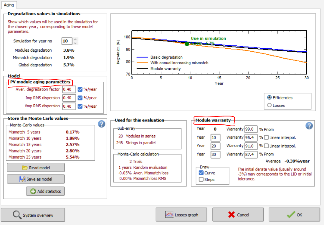
Thank you very much, Then I guess "Module warranty" values have nothing to do in the simulation? There is no need to input them and only using "PV module agging parameters" box is enough?
-
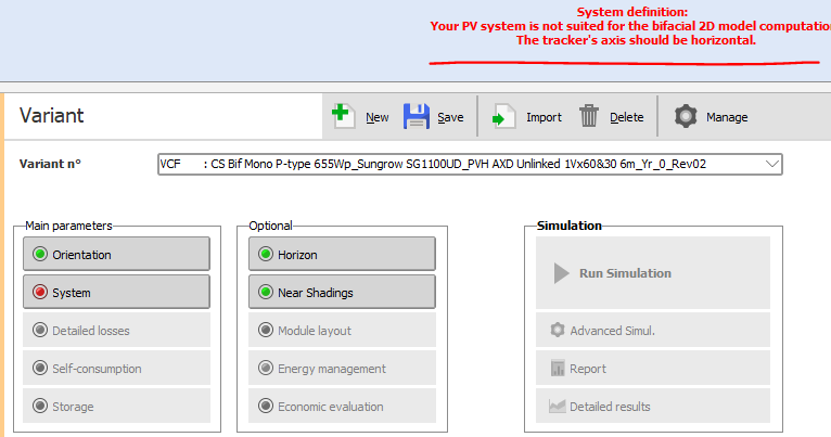
Hello, I am currently analyzing a 1P trackers' PV plant. One side of the plant is configured with 6m pitch while other uses 5m pitch. As I enter the 3D scene using these two tracker separation I get the following error as PVSyst is not able to compute such scenario: In blue and yellow the two different pitch we have: Anyone some advise on how to deal in this case? Thanks a lot!
-
Hello, Recently I've been wondering how to enter PV module aging parameters right as information online is a little confusing. I would really appreciate some light on this topic to try to answer the following: How should we enter "PV module aging parameters"? Where to get the info from? Is it right to enter "Module warranty" parameters using the specified in de module's datasheet? Are these parameters used in any kind of way in the simulation? Thank you in advance!
-
Hello Jax, Don`t know if you have any news about this issue. I find myself under the same situation. Thanks in advance.
-
Thank you André, Been checking my calculations and i am much convinced that they are correct. Yet, still don´t know why I obtain a different value for the PRtemp, must be then something odd with some value considered. Had done it using the hourly csv exported from the advanced simulation option. Thank you anyways
-
Hello, Recently I've been checking the results on PRtemp that PVSyst throws, based on the calculation they give in https://www.pvsyst.com/help/performance_ratio.htm which is indeed the one given by NREL and IEC 61724-1. Below the results for a yearly TArrayAver= 40,79ºC. You can see the reults given by PVSyst and, in red, the ones manually calculated using the formulas mentioned above: Date Month TArray GlobInc E_Grid PR PR PR PR temp °C kWh/m²/mth MWh/mth ratio temp ratio 01/01/1990 1 18,829 98,151 4592,1 0,900 0,850 0,900 0,857 01/02/1990 2 22,082 124,36 5801,4 0,897 0,859 0,897 0,864 01/03/1990 3 26,722 176,88 8113,6 0,882 0,860 0,882 0,862 01/04/1990 4 30,465 216,64 9692,9 0,860 0,848 0,860 0,851 01/05/1990 5 37,29 270,47 11559 0,822 0,830 0,822 0,831 01/06/1990 6 42,159 292,54 12333 0,811 0,832 0,811 0,834 01/07/1990 7 47,381 321,19 13209 0,791 0,825 0,791 0,828 01/08/1990 8 47,486 288,4 12333 0,822 0,854 0,822 0,861 01/09/1990 9 40,079 212,27 9308,6 0,843 0,858 0,843 0,861 01/10/1990 10 32,068 154,07 6954,4 0,868 0,858 0,868 0,863 01/11/1990 11 23,085 103,25 4766,7 0,888 0,852 0,888 0,857 01/12/1990 12 18,789 88,653 4127,8 0,895 0,847 0,895 0,853 Yearly total 33,785 2346,9 102791 0,842 0,845 0,842 0,842 Does any one know how PVSyst calculates the PRtemp values? Seems like they are not using the formulas described in their manual. Thank you!
-
Modeling two different module using One central Inverter
jonipa replied to mohsinsanaullah's topic in Simulations
Hello, wouldn't this trick increase value of the parameters EOutInv, EArrayMPP and EArray among others? Since now the inverter has more MPPTs, does it affect in any way PV field or inverter production? Thank you. -
As beforehand I don't know which one is more restrictive, guess the better option is to modify inverter's output power. It should be applied to Pnom as weel as Pmax, right?
-
Thank you Michele, So what if I have a limitation of, for example, 46MW at injection point and also a 47 MW limitation at inverter level? How should it be managed when inputing it into PVSyst?
-
Maybe @dtarin could give us some light on how to proceed?
-
Hello! I am currently trying to understand how to manage the case in which there are two power limitations in my PV Plant: Grid and inverter limitation. PVSyst seems to only allow the limitation either at inverter or at injection point level. At least in the "energy management" section. Is ther a way to apply both? Maybe applying inverter active power limitation directly on inverter .ond file? What is the right way of doing it? Thank you for your feedback!
-
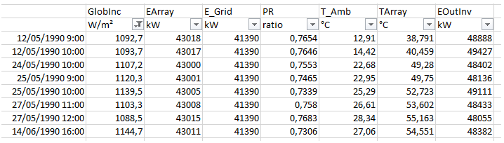
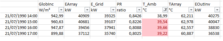
Hello! I was recently analyzing some data from the advanced simulation excel output and found the following results: Taking a look, for high irradiance values Earray is lower than EOutInv. Does anyone know how is this possible? From the same file, other values seems to be OK, as EOutInv is lower than Earray: Thank you!
-
Right, I'll check. Summarizing, I understand the two options as follows, seeming 2 as the more accurate one: If input the total number of transfos: Average the total power losses (∆Ptotal / num transfos). If input only one transfo: Input the total power losses and add up all the no-load loss, full-load loss and power in the transformer data.