

Lazare Fesnien
-
Posts
276 -
Joined
-
Last visited
Posts posted by Lazare Fesnien
-
-
Hi,
Sorry for the inconvenience, this is due to a bug present in the version, these various problems have been resolved in our patches
-
Hi,
We update the database using the requests of the manufacturers, and publish it with each new issue of PVsyst.
We can't of course follow all the new products of all manufacturers in the world. We don't want to include data without the acknowledgement of the manufacturer.
The creation of a pump is quite complex, please send me the technical sheet in PDF format so that I can provide you with the component
-
Hi,
We update the database using the requests of the manufacturers, and publish it with each new issue of PVsyst.
We can't of course follow all the new products of all manufacturers in the world. We don't want to include data without the acknowledgement of the manufacturer.
Nevertheless you can easily create your own components by yourself. The easiest way is to choose a similar existing device in the database, modify its parameters according to the manufacturer's datasheets, and save it under a new name, therefore creating a new file in your database.
You have a tutorial for that on youtube: https://www.youtube.com/c/PVsystTutos, page Component database
The optimizer's properties and operating conditions are very specific to each manufacturer.
We need a close collaboration with the manufacturer for implementing them in PVsyst.
-
Hi,
This appears if you have defined your inverters by "MPPT input", is this the case?
-
Hi,
When one or several cells are shaded, the whole sub-module becomes reverse-biased, the by-pass diode is activated above the current corresponding to the residual power of the diffuse part.
This results in a quite different situation as the previous one: the true Pmpp maximum is decreased in voltage (voltage of each sub-module, plus the diode reverse voltage), but the current remains the same Impp.
When you have one only string, the Vmpp of the string is reduced but the Impp current is identical for all modules, so that the Pmpp of the string remains the sum of the Pmpp of all modules.
However the voltage of this Pmpp may be (often) below the voltage threshold (VmppMin) of the inverter.
With several strings in parallel on a single MPP input, this reduced Vmpp induces a severe mismatch.
As a consequence the optimizers don't have anything to recover with partial shadings on a single string.
-
Hi,
This will no doubt be developed soon.
At the moment this option is not yet available
-
Hi,
This happens if you pump more than the drill can.
The deep well is defined by a dynamic level and a drawdown, if your PV field and your pump are oversized, you will pump faster than the regeneration of the deep well
-
Hi,
We update the database using the requests of the manufacturers, and publish it with each new issue of PVsyst.
We can't of course follow all the new products of all manufacturers in the world. We don't want to include data without the acknowledgement of the manufacturer.
Nevertheless you can easily create your own components by yourself. The easiest way is to choose a similar existing device in the database, modify its parameters according to the manufacturer's datasheets, and save it under a new name, therefore creating a new file in your database.
You have a tutorial for that on youtube: https://www.youtube.com/c/PVsystTutos, page Component database
-
-
Hi,
The file may contain hourly or sub-hourly values, which after importing can be rescaled to match a given yearly consumption.
The simulation can then either use the values that were stored at the moment of importing, or import the file every time the simulation is started (see below).
The format of the columns in the CSV-file have to follow the PVsyst standard format described below.
Importing the file
Click on the 'Browse' button BrowseButton, navigate to the location where the file with the load profile is stored on your disk, and select the file. When the file is successfully imported, its raw contents is displayed on the bottom left part of the window.
Below the file name, several summary values will be displayed. You can find the average and maximal load, as well as the total yearly consumption. It is possible to rescale the yearly consumption to a given value, in order to match the profile to a measured or expected consumption.
If you go to the Tab 'Graph', you can view the imported profile as an hourly time series or as integrated daily or monthly values. A smaller preview of this graph is shown on the first tab.
Selecting a template
To simplify the use of typical load profiles, there is a drop-down selection of preexisting templates. The list shows all CSV-files in the Templates sub-folder of the current PVsyst workspace, which have a file name starting with 'LOADPROFILE_'. Selecting an entry from this list will automatically load the corresponding file.
To populate the Templates folder with some example files, you can select 'Reload Templates' in the workspace manager dialog. The examples are taken from the BDEW website, the German grid operators association. There are eleven examples in total, which are summarized in the table below. All profiles are normalized to a consumption of 1MWh per year. For more details please visit the BDEW web page for typical load profiles (in German).
Profile
File Name
Description
Household_BDEW_H0
LOADPROFILE_Household_BDEW_H0.CSV
Typical profile for private household
Commercial_BDEW_G0
LOADPROFILE_Commercial_BDEW_G0.CSV
Weighted average of the commercial profiles G1-G6
Commercial_BDEW_G1
LOADPROFILE_Commercial_BDEW_G1.CSV
Commercial with no weekend activity
Commercial_BDEW_G2
LOADPROFILE_Commercial_BDEW_G2.CSV
Commercial with mainly lighting consumption
Commercial_BDEW_G3
LOADPROFILE_Commercial_BDEW_G3.CSV
Commercial with close to constant consumption
Commercial_BDEW_G4
LOADPROFILE_Commercial_BDEW_G4.CSV
Commercial following teh common shopping opening hours
Commercial_BDEW_G5
LOADPROFILE_Commercial_BDEW_G5.CSV
Commercial, Bakeries
Commercial_BDEW_G6
LOADPROFILE_Commercial_BDEW_G6.CSV
Commercial with increased weekend activity
Agricultural_BDEW_L0
LOADPROFILE_Agricultural_BDEW_L0.CSV
Weighted average of agricultural profiles L1 and L2
Agricultural_BDEW_L1
LOADPROFILE_Agricultural_BDEW_L1.CSV
Agriculture, dairy
Agricultural_BDEW_L2
LOADPROFILE_Agricultural_BDEW_L2.CSV
Agriculture linked to a household
You can also add your own templates to the 'Templates' folder in the PVsyst workspace. Files having a name that starts with 'LOADPROFILE_', will show up as an entries in the templates selection.
Using the profile in the simulation
In the dialog you can specify how the values from the file will be used in the simulation:
ValueStorageSelection
-'Store internally' is the default choice. The imported values, including a possible rescaling, will be stored in the variant and these values will be used in subsequent simulations. Any future changes in the original data file will have no effect on the stored values, unless you import them once again. However, if the rescaling factor is changed, the values will be multiplied with the corresponding factor.
-When selecting 'Read the file', PVsyst will copy the file to the folder 'UserHourlyParams' in the PVsyst workspace. From there, it will read the file every time the simulation of the variant is launched and, if defined, apply the rescaling factor. These values will then be stored in the variant, together with the simulation results. This mode is particularly useful when changing the load profile in the batch mode.
Sub-hourly data
The files with the load profiles may contain sub-hourly data (for example load profiles in 15-minutes steps). Since the PVsyst simulation proceeds in hourly steps, this data will be converted into hourly values when the file is imported.
The time step and the correct handling of the values are automatically recognized according to the date/time stamps and the specified units. Power units in [W] or [kW] will be averaged, Energy units in [Wh] or [kWh] will be summed within each hour.
Hourly Parameters file
The ASCII input source file can be prepared in a spreadsheet program (like MS-EXCEL), in the CSV-format (Comma Separated Values, separator may be semicolons or commas).
You can find a template named "PARAMS_Hourly_Template.CSV" :
- either in the program's location, usually C:\ program files (x86) \ PVsyst7.x \ DataRO \ PVsyst7.0_Data \ Templates \.
- or in your workspace C: \ users \ YourSession \ PVsyst7.0_Data \ Templates \.
In the latter case you can update/reload this file using "Files > Workspace > reload templates" in the main menu.
PVsyst standard format for hourly or sub-hourly parameters
The required format for the importing of hourly parameters in PVsyst is the following:
-Text file (CSV format with commas or semicolons) written in ANSI (not UTF8).
-All lines beginning with the hash symbol '#' are assumed to be comments, and will be ignored.
-Blank lines are ignored.
-The first line that does not start with #, holds the column titles. The first two columns should be "Date", and "P Load", further columns are ignored.
-The following line contains the units of the data in the columns. The date should have no units, the units for the load can be power ([W], [kW] or [MW]) or energy ([Wh], [kWh] or [MWh]).
-Then there follow the lines with the values, one line per data entry.
-The date and time in the first column can be given either in European format (DD/MM/YY hh:mm) or in US format (MM/DD/YY hh:mm).
-The file should contain all hours of a generic year (from 01/01 at 00:00 up to 31/12 at 23:00). Only day and month will be retained, the year will be ignored.
-These dates/hours do not need to be related to the dates of your input meteo file: they are for each hour of a generic year.
-
Hi,
When the components come directly from PVsyst, a mention appears in the report "original PVsyst database", if a user modifies an element in a component, the mention changes to "Custom by user"
-
Hi,
In the detailed losses window, you must click on "Ohmic losses"
The ohmic resistance of the wiring circuit induces losses ( ELoss = Rw · I² ) between the power available from the modules and the power at the terminals of the sub-array.
The relevant parameter for the simulation is the Rw value, which is an equivalent resistance of the wires, as "seen" from the input of the global sub-array (i.e. the set of MPPT inputs defined in this sub-array). You should define one Rw value for each sub-array in your system.
First stage evaluation: percentage of STC
The Rw value evaluation will highly depend on the sub-array structure.
However PVsyst provides a convenient way of defining a default value to be used during the first stages of the study of a PV system.
We specify a Power loss ratio with respect to the STC power.
We can consider the equivalent "resistance" of the STC operating point: RarraySTC = Vmp / Imp (at STC) [ohm].
Then the Wiring loss fraction = Rw / RarraySTC (ratio, or percentage).
In PVsyst we have chosen a default initial value of 1.5% (at STC) for this usual loss. This default may be modified in the Hidden parameters ("Default Wiring Resistance loss ratio at STC") for the initialization of any new project/variant.
Loss in the simulation
The ohmic losses behave in a quadratic way with the array current: Ploss = Rw · Iarray².
Now if the array is not operating at STC, the wiring loss fraction will become:
Ploss / Parray = Rw * Iarray² / (Varray * Iarray) = Rw * Iarray / Varray.
i.e. proportional to Iarray. This means that at half the irradiance (half the current), the wiring loss fraction will be half, etc. Therefore the Wiring energy loss has to be evaluated at each hour of the simulation, and accumulated in terms of energy.
The final result of the Ohmic wiring loss (in terms of percentage) as shown on the loss diagram will be from this hourly energy balance. It is usually of the order of 60% of the Loss fraction specified a STC.
Final calculation: evaluating the resistance
In the latest stages of the project, the equivalent wiring resistance should normally be calculated according to the real lengths and sections of the installed wires.
The program offers a special tool intended to optimise the wire diameters at each stage of the array.
-
Hi,
Many topics and questions are covered in our videos on our youtube channel: https://www.youtube.com/channel/UCMzsEWHk3f7XD_dg1lngmzg?view_as=subscriber
and others are available from our HELP file:https://www.pvsyst.com/support/
If you have more specific questions, you can contact PVsyst support http://support@pvsyst.com
-
Hi,
The "system" is defined as the set of components constituting the PV-array, i.e. the PV modules, strings, inverter, up to the connection to the grid.
Sub-array definition:
You can define an unlimited number of different sub-arrays kinds (add, copy, rename, move and delete on the right of the dialog).
For a given subarray: you have to define your requirements, and PVsyst will automatically propose a suited arrangement.
The basic requirements for a sub-field (i.e. the parameters you should input) are:
- The desired nominal power, or alternatively the available area for installing modules,
- A PV module model, chosen in the database.
- The inverter model, chosen in the database,
Then the program will choose the required number of inverters, according to a pre-defined Pnom array/inverter ratio of 1.25.
It will then propose a number of modules in series, and a number of strings in order to approach the desired power or available area.
The acceptable choices for the number of modules in series/parallel are mentioned on the dialog. They should meet the following requirements:
- The minimum array voltage in worst temperature conditions (60°C) should not be under the inverter's voltage range for MPPT,
- The maximum array voltage in worst temperature conditions (20°C) should not be above the inverter's voltage range for MPPT,
- The maximum array voltage in open circuit (Voc at -10°C in Europe) should not exceed the absolute maximum voltage at the input of the inverter,
- The maximum array voltage in open circuit (Voc at -10°C in Europe) should not exceed the allowed system voltage specified for the PV module.
NB: The Voltage values calculated by PVsyst for Amorphous modules are the stabilized ones after degradation. The initial values may be up to 15% higher during the first months. This should be taken into account when sizing the system, especially concerning the absolute maximum voltages for the inverter input or the module insulation.
The inverter power sizing is a delicate and debated problem. PVsyst proposes a methodology based on the predicted overload losses. This usually leads to Pnom ratios far below those recommended by inverter's providers, but we think that they are closer to an economical optimum.
All these conditions are explicitly displayed on a system sizing graph, (button "Show sizing").
You can now play with these parameters taking your own constraints into account. You can retrieve the automatic proposed values by clicking on the associated checkbox.
Warning messages will be displayed if there are some incompatibilities between the chosen parameters. Red warnings are not acceptable (simulation cannot be performed) and orange warnings are indicative. These colours will be thrown back on the "System" LED's button.
NB: The sizing temperatures - as well as other parameters like the allowed loss when using highly overloaded systems - when may be adjusted :
- for your project in the project's parameters (button "Project's settings")
- as default values for any new project: in the "Hidden parameters".
You can have a look on our FAQ "How to adjust the design temperatures" for reasonable values of these temperatures. In principle, except the Minimum temperature, you don't need to adjust them.
If desired (in a second step of the development of your project), you can
- modify the PV-array specific loss parameters (thermal, wiring resistance, module quality, soiling, mismatch, IAM) with the "Detailed Losses" button.
- define a user's load profile for determining the owner's own consumption and the injected (sold) energy to the grid (net-metering). You will usually define an hourly profile in order to take realistic daily production and consumption distributions into account.
-
Hi,
To be sure of the correct use of batch mode, a Youtube video is available on youtube:
-
Hi,
Are you sure that your number of modules in series and in parallel are identical?
For more information on inverter sizing please read:https://www.pvsyst.com/help/inverter_array_sizing.htm?zoom_highlightsub=inverter+array+sizing
-
Hi,
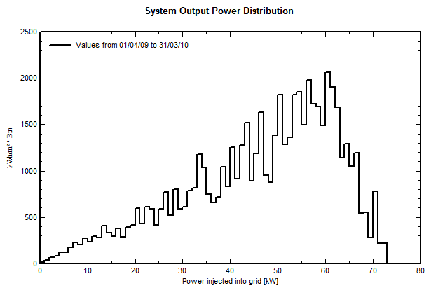
you can get a distribution of the Output power.
Please open "Detailed resullts > predef graphs", and here you can choose "System output power distribution". This will give a distribution like this:
You can also produce a CSV file of hourly values, for use in EXCEL. For this, please uses "Advanced simul. > Output file". Here press F1 for the procedure.

-
Hi,
The power optimizer definition and behavior are specific for each technology (and each manufacturer).
Therefore there is no general database, but only a list of available devices. The specifications are defined by the Manufacturers, and are not modifiable. You cannot add a new device by yourself.
After checking "Uses Optimizers" in the System design dialog, you will get a List of all available devices. The optimizers suited for your pre-defined PV module will appear in green.
You can get the Optimizer's specifications within the Optimizer's dialog, which is only available by the button "Open" after having chosen to use an optimizer.
This dialog proposes:
Main parameters : The parameters as defined in the database. Their nature and values are specific for each technology.
Input modules: Shows the limits (Voltage, Current, Power) for the connected PV module. In some cases you can specify here to connect several modules in series or parallel on one optimizer input.
Output I/V behaviour: The behavior is very specific to each technology. This pedagogic tool tries to explains the principles, by showing the I/V or P/V input and output curves in diverse situations.
This explains different kinds of mismatch, and the electrical shading of modules and sub-modules (you can modify the number of shaded sub-modules in each module).
As an example, it shows the effect of adding 4 optimizers in series.
Efficiency profile: The optimizers are not quite perfect; they suffer of a little inefficiency as specified here. The efficiency may be dependent on the "optimizing ratio" (current "buck ratio" or voltage).
Sizes: Usual page for sizes and comments. Pay attention to specificities for the use of some of these optimizers (suitability, compatibility, etc)
-
Hi,
You can get a custom graph using "Advanced simul > Special graphs". Here you can define any graph to be produced by the simulation.
Or produce a CSV file of hourly values for any variable, using "Advanced simul > Output file"
-
Hi,
Indeed, this will lead to a "stop" of the inverter because in the data sheets of the inverter VminMppt = VminInverter
This will therefore lead to a loss which will be reflected in your simulation.
-
Hi,
Currently, degradation only affects PV modules. Regarding the batteries, the degradation is not yet taken into account in the calculations.
The DOD parameter is of course taken into account for the calculation of the stored energy.
In the "Economic Evaluation" tool, you can plan a battery replacement after x year in order to accurately calculate your ROI and LCOE
Regards
-
Hi,
A new patch V7.2.10 is available on our website resolving this issue.
Please test this feature on this patch and tell me again if the problem still appears.
Sorry for the inconvenience
-
Hi,
This report is very strange, some default information from PVsyst is missing.
Are you sure you are using the official V7.2.9 version?
A bug appeared in the report display, this will be fixed in the next patch
-
Hi,
As you can see from the technical datasheet of the inverter, the output power at 250KVA is given at 30 ° C and the output power at 225 KVA is given at 40 ° C.
A profile of the maximum AC power as a function of the temperature can be defined in the "output parameters" tab of the inverter.
The components supplied by the manufacturer are verified so the data is consistent.
Please check in your "CUSTOM" OND file that the maximum power parameter has been modified
PAN file to simulate Akuo PV panels
in PV Components
Posted
Hi,
We update the database using the requests of the manufacturers, and publish it with each new issue of PVsyst.
We can't of course follow all the new products of all manufacturers in the world. We don't want to include data without the acknowledgement of the manufacturer.
Nevertheless you can easily create your own components by yourself. The easiest way is to choose a similar existing device in the database, modify its parameters according to the manufacturer's datasheets, and save it under a new name, therefore creating a new file in your database.
You have a tutorial for that on youtube: https://www.youtube.com/c/PVsystTutos, page Component database