
Lazare Fesnien
-
Posts
276 -
Joined
-
Last visited
Everything posted by Lazare Fesnien
-
Hi, Inverters with Unbalanced MPPT inputs Some special inverters (namely in the Tripower series of SMA) have 2 MPPT inputs with very different powers. In practice this is very useful as you can define an array without much constraints about the module number on the main input, and one string with the remaining of your modules to be installed - whatever their number - on the secondary input. This feature is part of the Inverter's definition. With these very special unbalanced inverters, when defining a sub-array you will have the choice between "Main" and "Secondary" MPPT inputs. In principle you should define sub-arrays for the same number of "Main" and "Secondary" inputs (i.e. use all the available inputs). However the button "adjust" gives the opportunity of not using the secondary input. Please check with the manufacturer that this is really possible with the real inverters you are using. At the design time, the nominal powers of each input are evaluated according to the maximum currents specified for each MPPT inputs. This may sometimes lead to unacceptable overload losses. If this warning is red (error), you have to increase the allowed overload energy loss in the "Project's" parameters (button "Albedo-Settings"). At the Simulation time, the power sharing (as mentioned above for normal MPPT inputs) is automatically performed as function of the PV modules connected in each sub-array. The Pnom of each MPPT input is evaluated just before the simulation. Example of use (tutorial): Suppose you have to build a PV system using 155 PV modules of 250 Wp, i.e. 38.75 kWp. 1. - Choose the inverter(s), according to a reasonable PNom ratio of 1.25: you need inverters for PNom(ac) = 38.75 kW / 1.25 = 31 kW. 2 inverters with unbalanced MPPT, of PNom = 15 kW should be well suited. 2. - In the "System" part, Define 2 sub-arrays, 3. - First one: define "Main" input with 6 strings of 20 modules (i.e. 120 modules), and 2 "Main" inputs: you get a PNom ratio = 1.25, quite correct. 4. - There are 35 modules left to be attributed. This will correspond to 2 different "Secondary" inputs, so you have to increase the number of sub-array to 3. 5. - Sub-array #2, define 1 "secondary" input, and attribute 18 modules. 6. - Sub-array #3, define 1 "secondary" input, and attribute 17 modules. 7. - Now the Warning "The inverter power is strongly undersized" appears in red, because the Overload loss is over 3% (depending on the meteo). You have to increase the "Limit overload loss for design" in the project's definitions. Now your system is ready for the simulation.
-

is there anyone tell me how to make an ond file?
Lazare Fesnien replied to wiki zhang's topic in How-to
Hi, We update the database using the requests of the manufacturers, and publish it with each new issue of PVsyst. We can't of course follow all the new products of all manufacturers in the world. We don't want to include data without the acknowledgement of the manufacturer. Nevertheless you can easily create your own components by yourself. The easiest way is to choose a similar existing device in the database, modify its parameters according to the manufacturer's datasheets, and save it under a new name, therefore creating a new file in your database. You have a tutorial for that on youtube: https://www.youtube.com/c/PVsystTutos, page Component database -
Hi, We update the database using the requests of the manufacturers, and publish it with each new issue of PVsyst. We can't of course follow all the new products of all manufacturers in the world. We don't want to include data without the acknowledgement of the manufacturer. Nevertheless you can easily create your own components by yourself. The easiest way is to choose a similar existing device in the database, modify its parameters according to the manufacturer's datasheets, and save it under a new name, therefore creating a new file in your database. You have a tutorial for that on youtube: https://www.youtube.com/c/PVsystTutos, page Component database With best regards,
-
Dear Salma, In the original PVsyst database we don't have the following model : STP370S-B60/Wnh_1500V_20V02_1756 I have checked your file "STP370S-B60/Wnh" : RShunt and RSerie values are unrealistic Please check your custom PAN files with the datasheet in order to be sure.
-
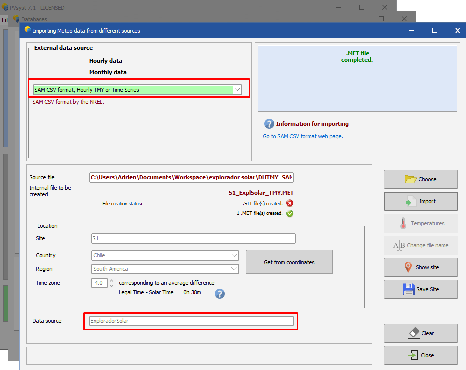
Dear soojin, The import worked correctly, what you imported was the multi-year hourly time series, which means every year is imported into separate .MET files (the one you have in your project is the last one for 2016). You can see in the screenshot below that the import creates 13 files for 2004 to 2016. This is done because PVsyst only simulates a single year of data. If you want to use all 13 years, you can look into the Aging tool or the Batch simulation. If you want a single file that represent the average for your place, you have to import the TMY with Sam format, see below for which source to chose. Regards, Lazare

-
Hi, Many issues are fixed in higher versions. You can download V6.88 or use V7.1 (download possible from the site : https://www.pvsyst.com/download-PVsyst/) Regards, Lazare
-
Warning messages will be displayed if there are some incompatibilities between the chosen parameters : - Red warnings are not acceptable (simulation cannot be performed) - Orange and Bleu warnings are indicative These colours will be thrown back on the "System" LED's button.
-
Hello, Please refer to the following topic : https://forum.pvsyst.com/viewtopic.php?f=17&t=5068 Regards,
-
In the meantime, you can already update to v7.0.14 by performing the following steps : 1. Uninstall 7.0.12 from Windows System settings – Add or remove programs (type programs in Windows search bar) and add PVsyst to the search list like displayed in the following screen capture: 2. Then you have to download last version (v7.0.14) from our web site: https://www.pvsyst.com/download-PVsyst/ Sorry for the inconvenience and best regards.