samastor
-
Posts
13 -
Joined
-
Last visited
Everything posted by samastor
-
Axis Azimuth for tracking tilted or horiz N-S axis
samastor replied to smishra24's topic in Shadings and tracking
Hello, The axis azimuth is to be used in cases where the orientation of the axis is deviated from the North/South axis. Meaning that the pv modules axis is not aligned with the North/South axis. Typically such deviation is to be avoided when planting a new system but if the land conditions and/or obstacles do not permit so then you deviate the axis. It is always assumed that South is 0°. Hope i helped. If you need anything more let me know. -
But this is a problem of the software as real fields can't be restrained to accept "only" what the software accepts. There are numerous projects where we have installations with such layout thus impossible to obtain a relevant information related with the expected energy yield to perform analysis of data etc. One thing is what the software permits to allocate and the other thing is reality. And since reality is what should drive development that is the reason we keep asking for a solution or if there is any alternative idea. In PVsyst 5.74 for example it is stated clearly that for the tilted axis tracker: (Under Help/Near Shading/Backtracking strategy) Same is also said in the PVsyst 6.68 help BUT when you make a misaligned tracking plane system has no problem calculating the shadowing using backtracking option (providing a table of linear shadowing with a factor of 1 at all inclinations). So there has been development on this approach hence it is only applicable one way. Therefore any reply from someone from PVsyst development team would be highly appreciated. Thanks,
-
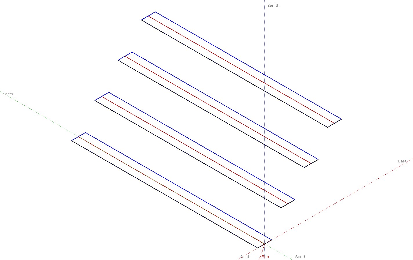
Good evening Of course i am dealing with the same problem, since misalignment can only be possible for tracking planes towards the West. I attach two shading scene examples. The East scene can be computed correctly. On the contrary the graphical result for the West scene can only be obtain using the negative pitch value thus computing is not available. Is there any solution to this with the current version? If not with the current version is it expected to be solved with the next one?

-
Short circuit Open circuit , Filling Factor values
samastor replied to Renu222's topic in Simulations
Good evening The shot circuit current is independent on the orientation and inclination of your system. It depends on the PV modules you are using. If you have more than one series in aprallel, the short circuit current of the installation would be the added value of the current on each serie. If you have only one serie of modules the short ciecuir current would be the one the module indicates on its data characteristics. Open circuir current would be 0. I believe you are referring to open circuit voltage. Again it depends of how you configure your system. Adding modules in serie you sum up their open voltage respectively. Fill factor, more commonly known by its abbreviation "FF", is a parameter which, in conjunction with Voc and Isc, determines the maximum power from a solar cell. The FF is defined as the ratio of the maximum power from the solar cell to the product of Voc and Isc. -
I believe that what you mean is on a given flat surface to fit more or less PV modules. This yes is related with the tilt. If you reduce the tilt, then the interow distance can be changed, maintaining the shadowing losses. And maybe this way you fit another row of modules, therefore more power. But most probably more power does not mean higher energy yield. The energy yield per kWp is the comparison. So for 1kWp or for 10MWp the figure should be the same (as long as the shading losses are maintained) Optimal angle represents the best posible angle for energy generation; achieve the highest energy yield per kWp. This is something that you can find easily using PVsyst When inside a project, meaning that you have defined the site location, go to Orientation. Choose Fixed Tilted Plane. On the bottom right you will see a button "Show Optimization". Clicking there the below part changes into graphs where the optimal angle and orientation is the peak value on the graph. Even if you do not press the button to see the graphs, the number there can give you the optimal angle (as you have the ratio between losses and optimal). When this % is 0.0 you have the optimal angle and orientation. Hope that i have understood what you are looking and i was helpful. Regards,
-
Since the meteo data you are using as a reference is horizontal irradiance data, it means that also any clouds are calculated throughout the year. When you see for example the hourly data you generate for the irradiance you can determine for example during summer some days where the global irradiance levels are significantly lower than other days. Therefore if you add some obstacles in your scene, you increase the losses of the irradiation for something that has been already "calculated". That is my opinion therefore if there is anyother point of view i would be glad to read it. Regards, Stavros
-
I am afraid that modelling it within a software would be a big challenge. On the other hand i do not understand why you look on the tree but not the forrest behind it. if you are concerned for the flickering shadowing of the wings of the wind turbine, then 99% you will have the post of the wind turbine bothering the PV installation. Therefore you will have for sure shadowing (partial) trhoughout the day related with the location of the wind turbines and the PV park. And i am more than sure that their shadowiwn losses could be easier accountable.
-
If you only change the tilt then you change teh geometry of the surface of your modules and not their power. Therefore the number of modules will not get affected by changing the positioning of your surface (either changing the tilt and/or orientation). Obviously the change in the positioning of the system may introduce changes in the energy yield.
-
Thank you André it seems that works if you apply the deviation in the object positioning. If i find any problem with the results, versus the recorded data i will come back to you. Have a nice weekend,
-
Good morning I am trying to perform some simulations with backtracking. Everything is fine while the azimuth of the tracker system is aligned with N/S axis. But the real system i want to simulate has a N/S deviation of 21° to West and the system does not give me the option to simulate such scenario. In means of PLC logic i have implemented the backtracking also under conditions of deviations on the North-South axis, just needed a bit more of trigonometry formulas but it works (based on observations early morning and late evening for the last 6 months in a location in Northern Spain). Is there any way i can simulate the system with PV Syst? Thanks in advance, Stavros
-
I do not face any problem using the database. I had imported module from Photon database as well as updating the characteristics manually for another module. The previous version of the PVsyst i have it shared in Wetransfer at the following link http://wtrns.fr/RJbk1ohq2njjVMr I have never done a downgrade though to tell you if it really works or not but you can give it a try (just in another computer than the one you use usually)
-
I think that the 5.58 has solved the problem with the difuse irradiation but not with the temperature. Still not importing temperatures using Firefox 13.0.1 Maybe is better to wait and use other browser until it gets check the compatibility? BTW Firefox has annoounced today a new version so better to verify the new version of Firefox (14) will be compatible. Thanks
-
As far as i have tested there is no problem with the irradiation import. I have tested 5 different sites throughout Europe (Spain, Italy, Germany and Greece) and has imported more or less correctly (beside in one site in Spain where February has been imported slighty higher - around 2%). I can confirm as well that temperatures are not longer imported. @Vinc if you want share the coordinates to run the import of that site as well.