PVsyst main changes
All Activity
- Today
-
Hi Bruno, You wrote: "It could happen that the DC is connected at a time when there is already a significant irradiance, but the ambient temperature is still low." But when the system is operating even at low temperatures, is there really a point in calculating the Voc voltage? In my opinion, at that stage the system is already in operating mode, so the voltage should be calculated based on Vmp, not under open-circuit conditions. That is, Voc can only be critical during system startup, and if the irradiance level is low, the system will transition into operating mode and everything will work properly. Am I right in thinking that considering only the worst-case scenario is not always the best approach, and that it's important to find a compromise?
-
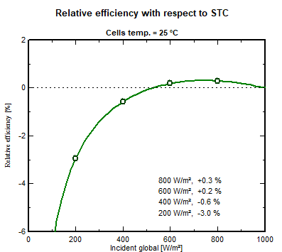
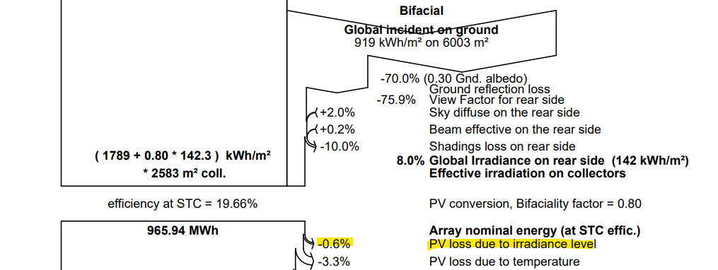
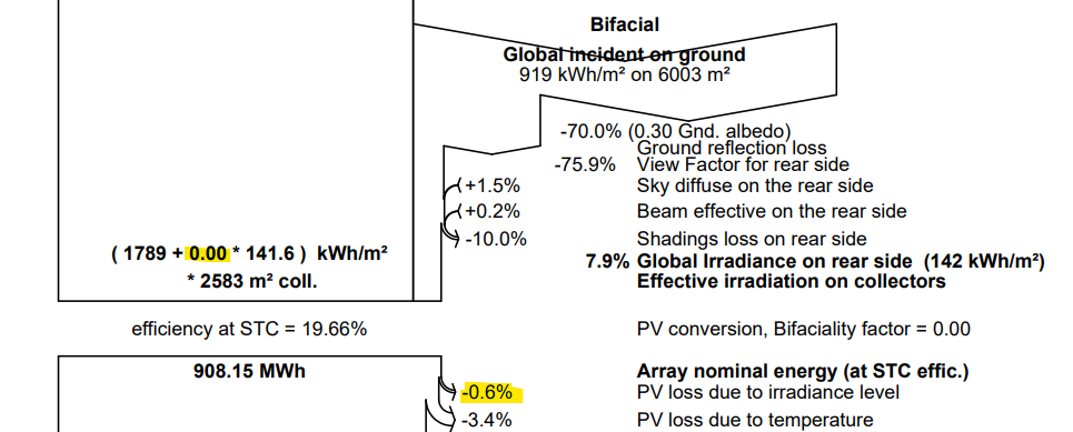
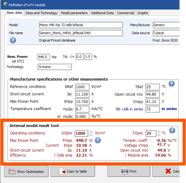
 Careful, the 200W/m2 I indicated was not refering to the rear side irradiance. It was a lower irradiance level, irrespective of whether the front or the rear recieves it. I would agree with your calculation only in the case where the front side doesn't recieves any light. Otherwise you cannot decompose the efficiency in two parts from front and rear, it doesn't add up linearly. You need to consider the full I-V curve under the effective irradiance of both front and read sides together. ----- Let's take other numbers to not create confusion again. If in certain scenario, the front side recieves 1000 W/m2 and the rear side e.g. 50W/m2, the module recieves an equivalent of 1000 + f*50 W/m2 of total irradiance. Let's say f=0.8, it is 1040W/m2. If the irradiance level is lower, let's say 5 times lower, the front side recieves 200 W/m2 and the rear side 10 W/m2. Thereforer, under low light, the module recieves an equivalent of 208 W/m2 in total. The curve of performance of the module as function of irradiance should be understood as function of this effective total irradiance. (Indeed, in the norms, when bifacial module are measured, the rear side is masked to not absorbed any light from the rear.) You can visualize this curve in the .PAN file: So whether the light comes from the rear or the front, it is the Incident global light that matters. For this specific curve, if the Incident global Incident global = front-side irradiance + (rear-side irradiance × bifaciality factor) is equal to 200 W/m2, the efficiency will be -3.0% lower than if the Incident global was 1000 W/m2. So any module PV module, bifacial or not, under given illumination condition will operate somewhere on this curve. If the module operates above the reference of 1000 W/m2, you have an efficiency degradation with respect to STC, between 500-1000 W/m2 (for this particular example), you have an efficiency boost, below 500 W/m2 you have an efficiency degradation. It doesn't matter if it is bifacial or not. However, the bifaciality has this influence that the module will operate at a higher illumination level than a monofacial counterpart (in the hypothesis they have exactly the same electrical properties), so at another position on this curve. But as you can see, it could well either mean an improved performance! PVsyst of course take this into account during simulation and you can find it in the loss diagram. For example if you use the "Demo Commercial Oakland" with VC6, you can see it there If for the sake of the test, you modify the .PAN file and set the bificiality factor to 0, you get then: Therefore, for this specific example, on the yearly production you don't see a specific loss difference due to the irradiance level operating further from STC between a bifacial and monofacial module. This is because this effect is small here (I would call it a third order correction). If you had a system with better Albedo for example, the comparison could be different.
-
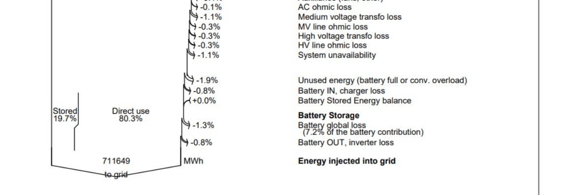
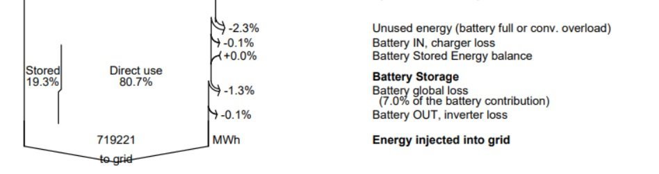
Why the battery stored % value increases when I decrease the efficiency of the converter and the inverter to 97% from 100%. 19.7% stored is with default converter and inverter parameters of efficiency. -0.8% loss of Battery IN & Battery OUT. Photo attached. 19.3% stored is with increasing the hypothetic converter and inverter parameters of efficiency to 100%. -0.1% loss of Battery IN & Battery OUT. Photo attached.
-
 SANKET PATEL joined the community
 -
 ok,I agree with your viewpoint, but do you think this calculation is reasonable? if the fornt side of module receive irradiance of 1000 W/m², and the rear side of module receive irradiance of 200 W/m², front side:(f × 22- f × 22) / (f × 22) = 0% (relative) rear side:(f × 21.34 - f × 22) / (f × 22) = -3% (relative)
 - Yesterday
-
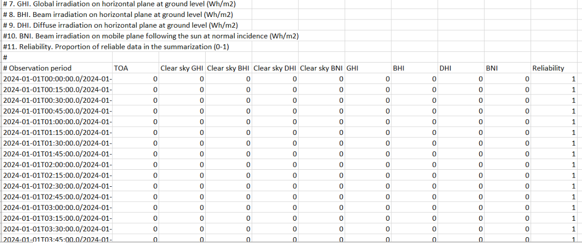
Currently, the only way to import sub-hourly data in PVsyst is to use the "custom file" import format. https://www.pvsyst.com/help/meteo-database/import-meteo-data/custom-meteo-files/index.html
-

Sigma Shifts for Gaussian Distribution Information
Auriane Canesse replied to rjv7888's topic in Simulations
The formula you have been applying is for a 2-sided test (~chances that the result is different, larger or smaller) whereas in this case a 1-sided test is appropriate (~chances the result is larger only) https://en.wikipedia.org/wiki/One-_and_two-tailed_tests -
norm.inv(Pxx,0,1). P99 is 2.33, not 2.35
- Last week
-
Clarifying Definitions to Avoid Confusion At PVsyst, the term "low-light performance" is usualy defined in the context of a PV module illuminated solely from the front side. Let’s consider the following example: At a reference irradiance of 1000 W/m², the module has an efficiency of 22% At a lower irradiance of 200 W/m², the efficiency drops slightly to 21.34% We define low-light performance as the relative difference in efficiency: (21.34 - 22) / 22 × 100 = -3% (relative) This means the efficiency at the lower light level is 3% lower relative to that at full irradiance. This is the standard definition used in PVsyst. Important Note: A more negative number (e.g., -4%rel or -5%rel) does not necessarily imply worse performance. In fact, it often indicates that the module performs better at high irradiance (1000 W/m²), which is an observed trend in modern PV modules, largely due to reduced series resistance Bifacial Modules and Rear-Side Illumination When it comes to bifacial modules, if only the rear side is illuminated (for the sake of the discussion), the module’s efficiency is proportional to the front-side efficiency, scaled by the bifaciality factor f. This factor applies equally at both high and low light levels. Therefore, the relative low-light performance of the rear side is identical: (f × 21.34 - f × 22) / (f × 22) = -3% (relative) Link to the Bifaciality Factor Definition To relate this to my colleague’s earlier explanation: the bifaciality factor is defined as the ratio of power output when the module is illuminated from the rear versus the front. This difference in power is primarily due to optical property differences between the two sides of the solar cell. Indeed: The cell materials are different on the front and rear sides Any differences in charge transport or extraction are negligible (These effects are much much smaller than the typical uncertainty in datasheet bifaciality (e.g., 80% ± 5%)) Thus, the bifaciality factor can effectively be understood as a scaling factor for the photogenerated current. In practical terms, the total irradiance received by a bifacial module can be calculated as: Irrad_Tot = front-side irradiance + (rear-side irradiance × bifaciality factor) The PV module performance modeling can then proceed without needing to differentiate which side the light is coming from—the model is agnostic to the direction of light incidence and so is the low-light performance.
-
Hi everyone! I would like to upload meteo data obtained from CAMS radiation service - SoDa. Particularly in intervals of 15 minutes, ¿is it possible or PVSyst just accepts above hourly registers? I also noticed that the information comes this way: Not any register about temperature. According to your post Meteo Database > Import meteo data > PVsyst standard format, that would be necessary so, in this case, how could I proceed? I only have GHI and DHI Thanks in advance. Óscar
-
 Ko Htoo joined the community
 -
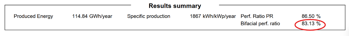
The bifacial performance ratio is only displayed on the report when the bifacial simulation is turned on (in System -> bifacial system -> use unlimited shed or tracker) The standard PR is not valid for bifacial systems because it does not include the incident irradiance on the panel back side. Since the production of the panel is the same in both computations, the PR is always higher than the BPR. https://www.pvsyst.com/help/project-design/results/performance-ratio-pr.html?#bifacial-performance-ratio
-
 UPDATE and correction to the previous answer. The "far" albedo (AlbInc, AlbHrz, AlbShd) and the "near" albedo (between PV rows, i.e. ReflFrt) should not be included in the same quantity to compare to POA measurements. The exception to this rule is the case of POA measurements that are made at the end of a row (such as in your case Luis). The problem with including both is that there is a risk of overcounting. For example in the case of a single row, AlbShd and ReflFrt do somwehat overlap. What this means is the following: if you measure POA away from the PV rows, or on the front row of the system, you can compare your measurements with GlobInc, or GlobHrz (which is like GlobInc but using the horizon profile as a shading). Between both, I'd rather use GlobHrz. Do not add ReflFrt. Instead, if you are measuring between the rows, the "far" albedo contribution should not be counted, and you should use ReflFrt instead. This means that you can compare to, e.g., GlobHrz - AlbHrz + ReflFrt. Note that if the POA measurement between rows is well below the top of the PV rows, then you should at least shade diffuse light, i.e., BeamHrz (horizon shaded beam) + CircHrz (horizon shaded circumsolar) + DiffShd (fully shaded diffuse) + ReflFrt (reflected irradiance between the rows). @Luis Zimmermann Sorry for the imprecise previous answers. This interaction between models is always a bit tricky. For your example, instead of BeamInc + CircInc + DifSInc + ReflFrt + AlbInc/2 + ( - HrzBLss - HrzCLss - HrzDLss - HrzALss/2) I would suggest now BeamInc + CircInc + DifSInc + ReflFrt/2 + AlbInc/2 + ( - HrzBLss - HrzCLss - HrzDLss - HrzALss/2)
 -
 Devanand B joined the community
 -
 Clarize joined the community
 -
I have the same question.
-
Hello, Can anyone help me clarify the sigma shifts on the website? Project design > P50 - P90 evaluations "NB: In the Gaussian distribution function, P90 represents a shift of -1.28 sigma, P95 => -1.64 sigmas, and P99 => -2.35 sigmas." I was expecting shifts of: P90 -> ~1.64 sigma, P95 -> ~1.96 sigma, and P99 -> ~2.58 sigma. Am I doing the math wrong or is there something else correcting/adjusting the sigma shifts? =NORMDIST(sigma.shift,0,1,TRUE)-NORM.DIST(-sigma.shift,0,1,TRUE) Thanks for the help!
-
 rjv7888 joined the community
 -
Hello, I am performing a yield simulation in PVSyst for a photovoltaic plant with single-axis trackers, oriented East-West, and bifacial photovoltaic modules. I imported the 3D model of the plant via the .pvc file generated with PVCase. The bifacial section of the modules in the System tab is properly filled out, and before running the simulation, I recalculate the shading table in the Near Shadings section. Why is it that sometimes the Bifacial Performance Ratio does not appear in the simulation report? Sometimes only a PR index appears, and it is also underestimated. Should I check some simulation parameter? Thank you for your help!
-
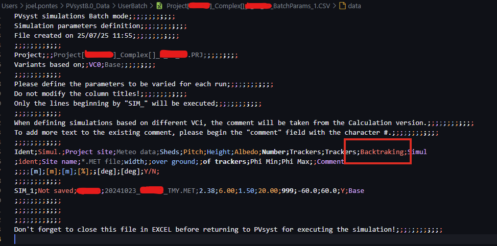
I assume that this question is about the Backtracking parameter in the batch mode. The way it works, is that in this column you can enter the characters Y or N for each simulation, and this will activate or deactivate the backtracking mode respectively.
-
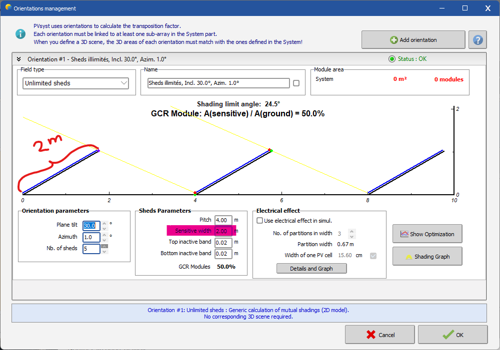
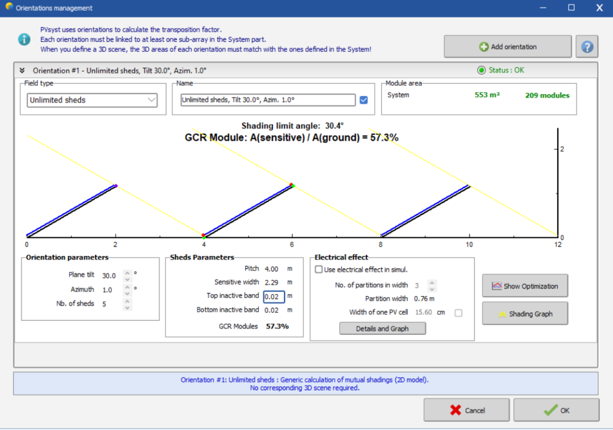
 Dear Oscar First of all, in the "unlimited shed" orientation, the sensitive width is the total width of the modules aligned on your PV table. For example, if your PV module is positioned in landscape in your 3D scene, the smaller side is 1.134 meters. Since you want two rows placed one above the other in each table (still in landscape), you need to multiply the smaller length by 2: 1.134 × 2 = 2.268 meters. In my example below, I used 2 meters as the sensitive width. You can always verify in the 3D scene whether the sensitive width value is correct. But if you already know the dimensions of your PV module, its orientation (landscape or portrait), and the number of rows per table, you can calculate the sensitive width. You can also click on the "Help" button in the "Show Optimization" window — it will open a help page with a full explanation (see below). If you need more information or something isn’t clear, don’t hesitate to reach out to us. Regards,
-
BNPI conditions cannot be used as input in PVsyst. You could use the BNPI test report to re-evaluate the bifaciality factor. But per se the BNPI result will not be used in the simulation (in which irradiance and temperature conditions vary at every step). To calculate the bifaciality factor the approach would be as follows. The basic equation is Pmeas(BNPI) = P(1000+phi * 135), and solve for phi (bifaciality factor). This could be solved by trial and error using the PAN file interface to evaluate P(irradiance, 25°C), but it will involve manual steps. Once you find which irradiance yields P(BNPI), you can easily find phi.
-
Currently, if the two-sided efficiency is applied, it is shown that only the Bifaciality factor is applied under the STC condition. Now, we are receiving the test report of the double-sided module under BNPI conditions, can we apply BNPI conditions?
-
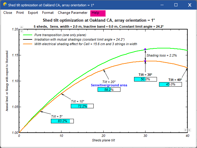
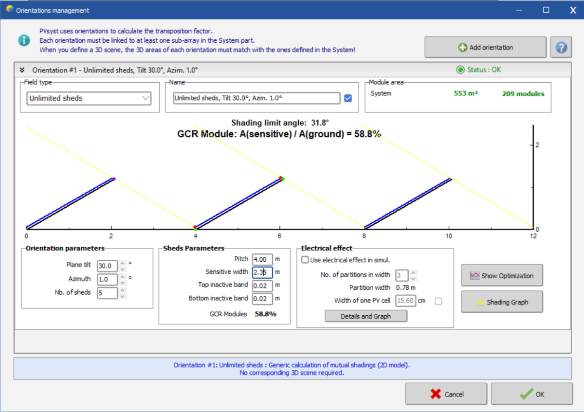
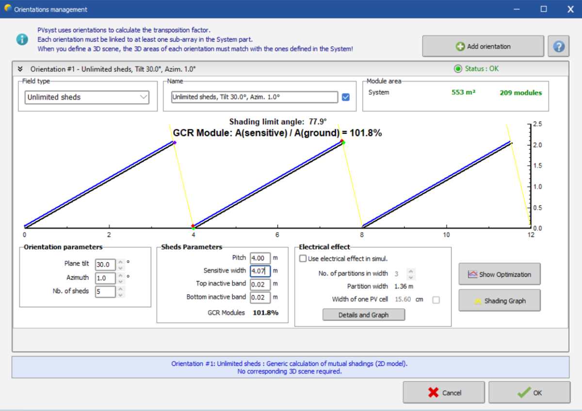
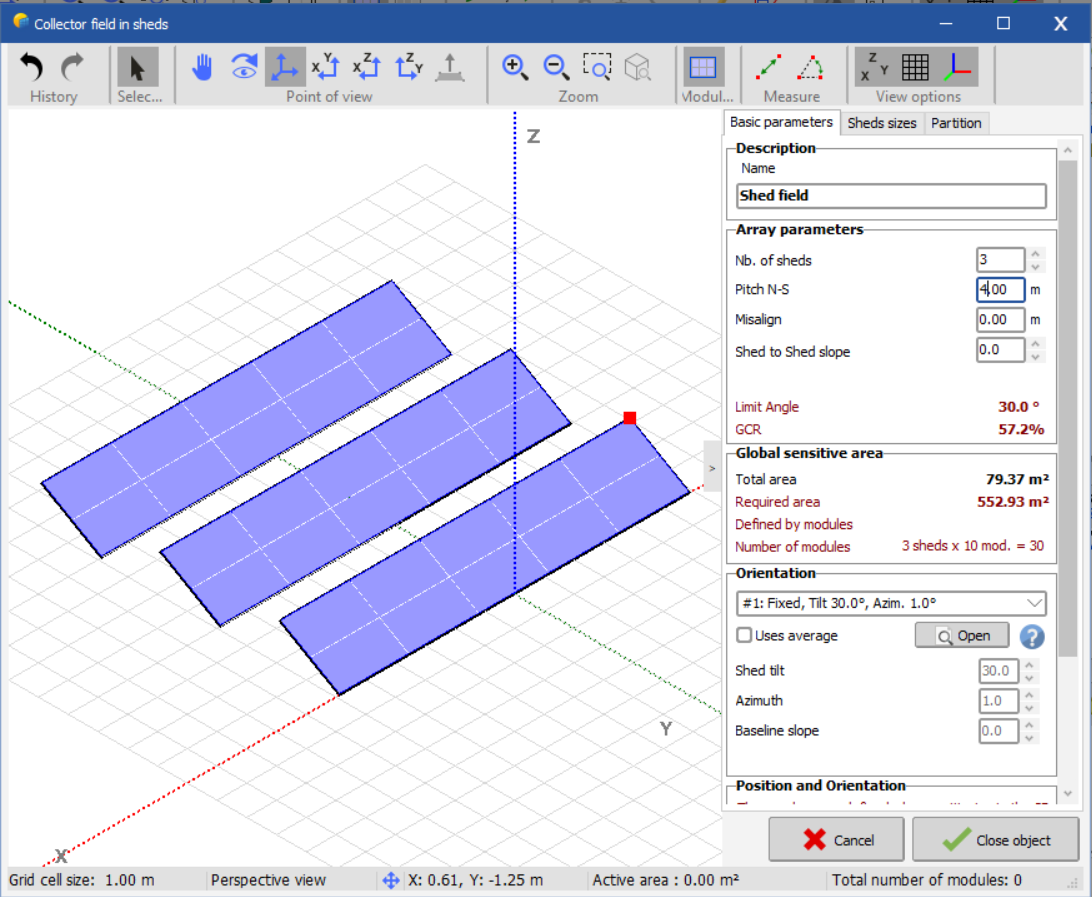
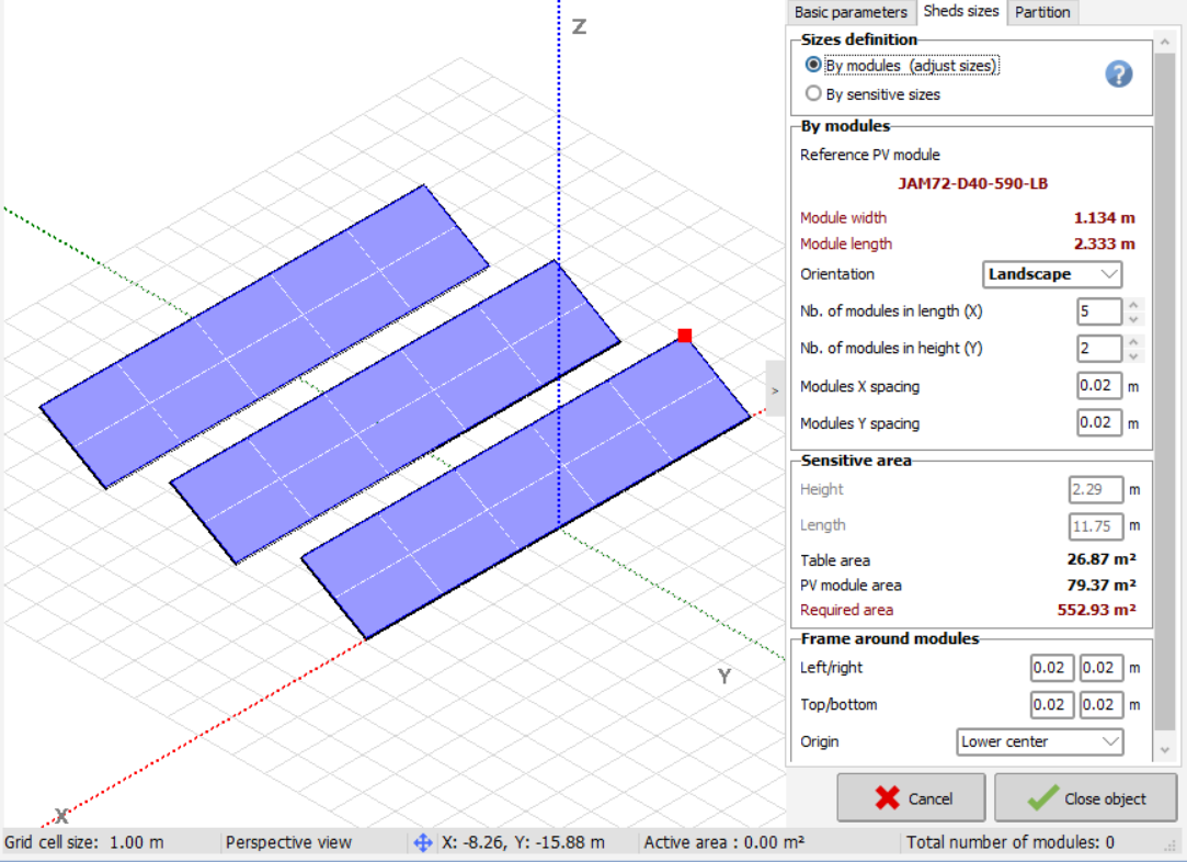
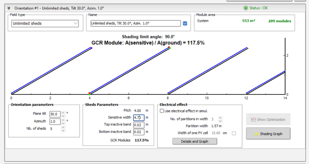
 Hello everyone, I am writing you in order to clarify something that I am missing right now. I first when to orientation management to try to check the optimization for my sheds with a tilt angle of 30º and 1º azimuth and 4 meters pitch. There, I thought that the Sensitive width would correspond to my panel length (one of 2.33 meters). In my case I am using in the 3D scene sheds of 2 modules in height so in total, that sensitive width would correspond to around 4.7 meters (2*2.33 plus 0.04 of inactive band). However, when I put the value, it proved that it should be wrong: So, I decided to go to the 3D shading scene and directly create my arrow of panels to try to discover what this width corresponded to. As you can see, this would be the limit angle and the GCR for such panels and such pitch: Looking at this, I thought that the heigh in the sensitive area above could be the widht introduced in the orientation , so I went back and introduced it: Looking at the Shading limit angle and the GCR it could be approximately (it is not exact) what the sensitive width stands for. However, this arises the question: is there not a way of knowing beforehand the sensitive widht? Do have I to go to the 3d shading to know this parameter and then enter it in the orientation management? Iam interested in the shading graph and the show optimization. I also though that it could be calculated with the sin30º or the cos30º with a hypotenuse of 4.7 meters (the length of the two panels in the shed). However, the closest value would be 2.35 meters (y) which also doesnt correspond to 2.29 meters... Hope I explained myself correctly. Thank you very much in advance.
-
Oscar Aviles joined the community
-
 StKog joined the community
 -
-
Hi, is there a recommendation for a Uc value for single axis tracker (N-S) with 1 modul portrait? Thanks
-
I understand. What I mean is, if the irradiation intensity on the back of the module is relatively low while that on the front is relatively high, so does it imply that the low-light performance of the rear side is worse?
-
Yes, actually the irradiance of front side + backside*bifaciality factor are put together, which gives an effective irradiance evaluation. Only after that, the PV conversion model applies. Indeed, the light reaches the same cells, be it from the front or the back. The same low-light performance is therefore taken into account for front and back (up to the bifaciality factor).
-
The temperature is generated from the monthly values saved in your site file, using the Meteonorm algorithm https://www.pvsyst.com/help/physical-models-used/synthetic-data-generation/index.html
-
Because the irradiance of the front side or the rear side of PV module will be different, in this case, there will be a difference in conversion efficiency between the front and back sides,with respect to 1000 W/m².