All Activity
- Past hour
-
Hi @Michele Oliosi, I, too, am looking for the individual inverter-level output data from the 8760. My system has 9 inverters. So, is it possible to get the individual inverter level generation data for each of the 9 inverters in separate columns after PVsyst simulation in the 8760 directly? Could you please guide me on this? Hi @solarDG1470, Did you figure out a way for this? Does PVsyst provide this data or is there some other way around? I would really appreciate it if you could share your knowledge on this. Thanks!
- Today
-
 Hello, The far albedo in the project settings, will be considered in all projects and correspond to the albedo of the surrounding of the project. The albedo in the bifacial system window is indeed only set for bifacial systems and correspond the the albedo of the ground just underneath the modules. This is not necessarily the same as the far albedo of the surrounding. Kind regards
 -
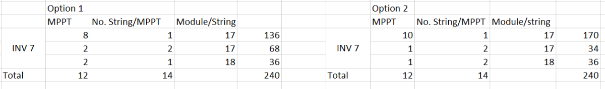
Hi everyone, I have a concern: will the simulation results be different with different configurations like below picture? I think it's yes in practical but in simulation, it shows not anymore different. Could anyone help me to understand this, please? Let's assume the model being used is SG125CX-P2

- Yesterday
-

Albedo shading component calculation
ClaireWest replied to ClaireWest's topic in Shadings and tracking
Sorry, the albedo shading factor should be *~65% and *~48% during these times, not sure what happened there -

Performance model IEC TS 61724-2 and IEC TS 61724-3
Michele Oliosi replied to cloudwalker's topic in Simulations
Hi, It's definitely possible. Currently the prerequisites for the EPI test are not very strict. It is about comparing total expected energies with measured ones, filtering for various contexts, with an hourly aggregation of measurements. PVsyst will generate a time series of results with various intermediate variables, that can help with filtering (e.g. for constrained periods). This time series can easily be compared with the measured one. For capacity testing (PPI), depending on the version of the standard -2, ed. 1 or 2, it is more or less easy to do. Ed. 1 should be straightforward. Ed. 2 has minute simulation as a prerequisite. Currently, PVsystCLI or PVsyst + batch can help implement a batch of 60 simulations (one for each minute in the hour) to mimic a minute-resolution simulation. This is a bit cumbersome, though. Luckily, we are working on PVsyst 8.1 which will simulate in minutes as well. The version is well underway (and the minute simulation is confirmed to work). This will make the ed. 2 capacity test straightforward as well. -

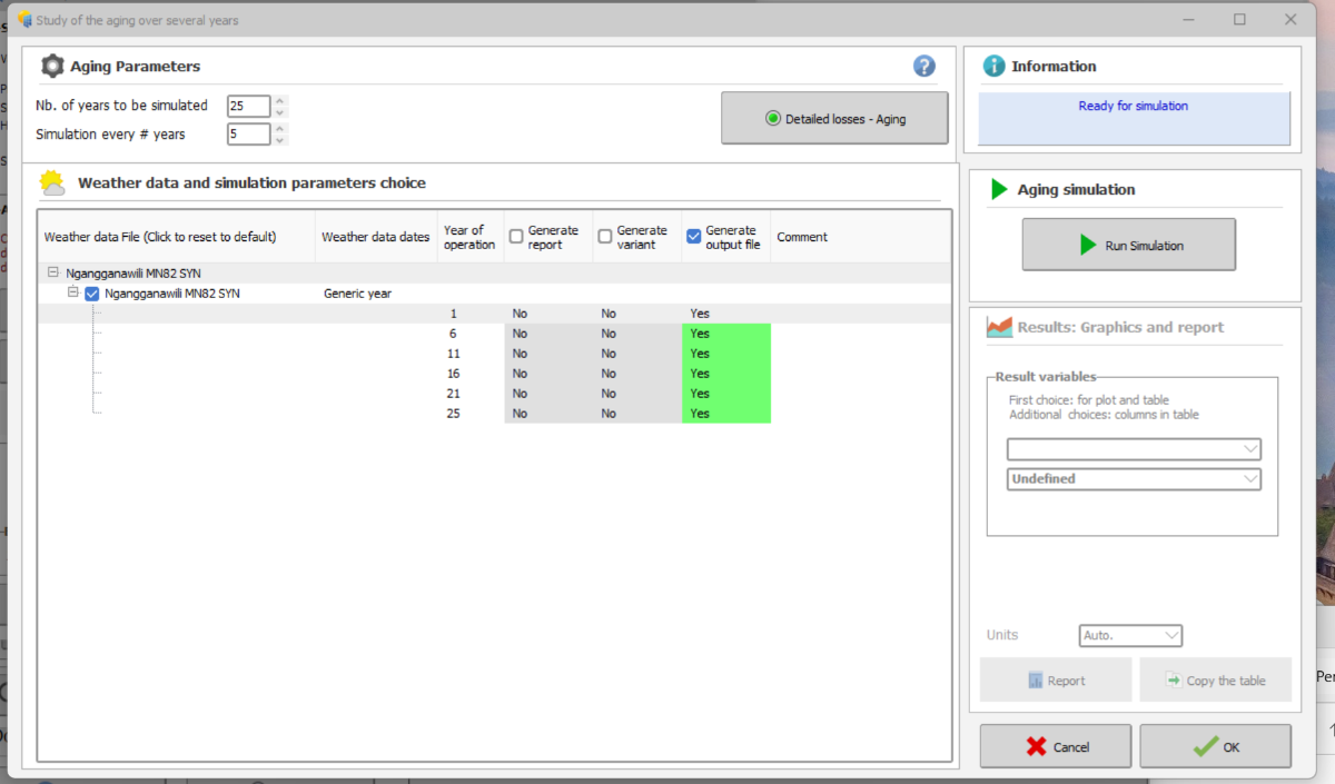
Generating an output file for later years using the aging tool.
Tonderai replied to Tonderai's topic in Simulations
Thanks dtarin, it worked! - Last week
-
 CKrening joined the community
 -
You can find more information here: https://www.pvsyst.com/help/physical-models-used/pv-module-standard-one-diode-model/pvmodule-structure/bi-facial-modules.html
-
 Dear PVsyst Team, I would appreciate your clarification regarding the definition and use of the Albedo parameter in PVsyst. In the software, the Albedo value appears in two different locations: Project Settings → Site → Albedo System → Bifacial System → Albedo Could you please clarify: What is the functional difference between these two Albedo inputs? In bifacial simulations, should both values always be identical for consistency? kind regards, Irakli
 -
Albedo shading component calculation
ClaireWest replied to ClaireWest's topic in Shadings and tracking
Thank you. Is that a fair assumption that only the first row is "seeing" the albedo? With typical GCR ~40% or lower there will be sun hitting the ground between the panels by early to mid morning. E.g. in my snip above (36% GCR), at 8am only 65% of the ground is shaded and at 9am only 48% is. So the albedo shading factor should be ~35% and ~52% during these times? -
 GSE PVT. LTD. joined the community
 -
Learn what bifacial factor means in solar panels, how it affects energy output, and why it is important for improving solar power efficiency and performance.
-
 harrybrook joined the community
 -

Generating an output file for later years using the aging tool.
dtarin replied to Tonderai's topic in Simulations
Go to output file, check the box "file name" under "output file". Set your variables. The name doesnt matter. Hit okay. Go to aging tool, have your ageing parameters set, I check both output file and report (to see everything ran correctly), click run simulation from within the ageing menu. it should output then. -
Hello Giancarlo, Do you have a valid license ? because this is one of the limitation of the DEMO mode. If you do have a license; please send us your logs at support@pvsyst.com: Regards; Laurent
-
I have a question: is it possible to set a layout zone and automatically fill it with the east-west table arrangement?
-
any updates on how to get around the demo version?
-
 Thomas joined the community
 -
 TSANTA RAMILISON joined the community
 -
Hi, I have modelled a solar farm installed 5years back and factored in the yearly degradation rates in the detailed losses>>aging section and enabled output file generation as attached below. For some reason, when I run the advanced simulation, it returns only Y1 E-grid values. How do I generate an output file with the hourly E-grid values for the current year, and later years? Thanks, Tonderai.
-

Why are diffuse integrals calculated for every run?
LauraH replied to LauraH's topic in Shadings and tracking
That would be great. -
Hola a todos, favor su ayuda. No puedo agregar un nuevo sitio en pvsyst, me aparece como deshabilitado la opción Nuevo
-
 Giancarlo joined the community
 -
Hello everyone, I have a question regarding the use of PVsyst for performance modeling in the context of performance testing (PPI and EPI) as described in the standards IEC 61724-2 and IEC 61724-3. Can PVsyst be used to generate a performance model that is suitable for performance testing according to these standards? Does anyone have practical experience with this? Is it possible to use 1-minute measured data in PVsyst for this purpose or what is the minimum data resolution supported for imported measured data? Thank you in advance.
-
 cloudwalker joined the community
 - Earlier
-
 outboardmotors3 joined the community
 -
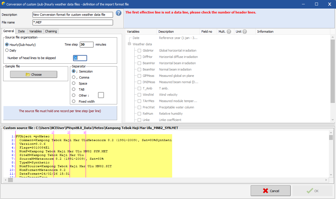
Hello, You should define the number of lines to be skipped, before the line where the (sub)hourly data starts. The general procedure for importing a custom weather data file is described in the following link: https://www.pvsyst.com/help/meteo-database/import-meteo-data/custom-meteo-files/conversion-protocol.html Note that you in this tool are supposed to import a a .csv file with (sub)hourly data, thus one line per time step with irradiance and temperature data and convert the .csv file to a .MET file that you can use in PVsyst to run your simulation. It seems like your source file is already a .MET file with Meteonorm 8.2 (hourly) data. You cannot re-convert an hourly .MET file to include the clipping correction.
-
Albedo shading component calculation
Linda Thoren replied to ClaireWest's topic in Shadings and tracking
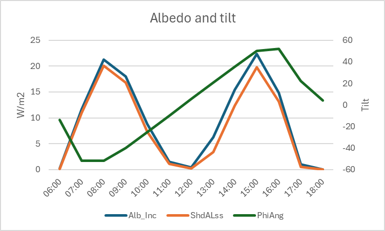
Hi, The shading calculation is indeed explained in the second link you have attached. In general, the higher the tilt, the higher the albedo contribution. Most of the albedo contribution will directly be lost (you see that the albedo loss is indeed following the albedo contribution) since we assume that only the first row is "seeing" the albedo, so that the albedo shading factor will be (n-1)/n (n = number of sheds). The albedo loss is a significant contribution to the global shading losses. -
 surronbuilds33 joined the community
 -
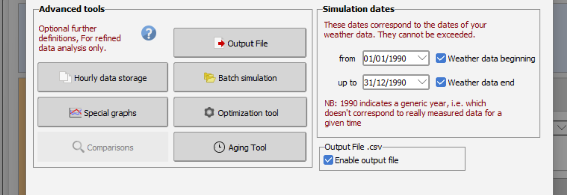
Hi, I am in process of applying the sub-hourly clipping and been following the instruction from INSTRUCTIONS FOR PREPARATION OF PAPERS, but i seem stuck at "the first effective line is not a data line, please check the number of header lines" Which data line should i refer? Do anyone have a video tutorial of enabling the sub-hourly clipping
-
 Haziq joined the community
 -
Why are diffuse integrals calculated for every run?
dtarin replied to LauraH's topic in Shadings and tracking
It would be helpful to include this in the next update. We've had to use custom tracker approximations to avoid long waits for diffuse recalculations when making other unrelated model updates. -
Hi, how is the albedo shading component (ShdALss) calculated? I have read the help pages on this topic but i am still not clear how this functionally works, sorry. https://www.pvsyst.com/help/project-design/shadings/calculation-and-model/index.html https://www.pvsyst.com/help/project-design/shadings/calculation-and-model/treatment-of-the-albedo-component.html#far-shadings Why does the albedo shading loss have this profile on a clear-sky day (single-axis tracking system): ? TIA
-
Why is the diffuse shading information computed for every run, unlike the direct shading? Can't this information at least be held in the active memory as long as you're working on the same variant? I'm tweaking my loss terms and every time I rerun, PVsyst takes the time to build the diffuse integrals again. I can understand if you don't want to save it in the export, but while you're working would be nice. Thanks.
-
Consideration of .PAN Parameters in Mixed Module Simulations
Linda Thoren replied to Elise's topic in Simulations
The low light performance and temperature coefficient is defined in the individual .PAN files. The thermal parameters are then set for the full system to evaluate the temperature and the thermal losses in each sub-array. Thus if you are mixing panels in the same inverter (though in different sub-arrays), the different temperature coefficient of the different modules are well taken into account. In the loss diagram you will see the results for the full system. You find more information on the subject in the following PVsyst help pages: https://www.pvsyst.com/help/physical-models-used/pv-module-standard-one-diode-model/index.html?h=pv+module+standard+one+diode+model https://www.pvsyst.com/help/project-design/array-and-system-losses/array-thermal-losses/index.html