All Activity
- Today
-
 By default we recommend Uv=0 as this coefficient is trickier to measure and varies even more from one PV installation to the next. There can be a large difference between the wind speed from a data provider (measured at 10m above ground, not always close by) and local conditions at the module level. But yes to be more accurate you simply need to measure this coefficients on your installation. https://www.pvsyst.com/help/project-design/array-and-system-losses/array-thermal-losses
 -

In-depth Inquiry on BIPV Aging, Temperature Modeling, and Loss Equations
Zahra replied to Zahra's topic in Meteo data
Thanks for respond, How about Uv? is there anyway to model it more accurate? -
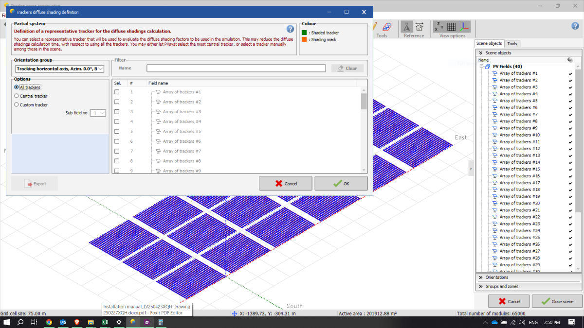
 Hi, A near shading loss of 2.8% for the system layout shown in your screenshot is within a reasonable range and you probably have to increase the pitch by a lot to see an effect on the near shading losses. The most accurate diffuse shading calculation will be obtained by using the "All trackers" option, as in your current example. For an exercise to better understand the impact of diffuse losses, you can instead select the "Custom tracker" option and choose a set of tables located at the very edges of the system. This option calculates shading only for the selected tables, then applies the same shading pattern to the rest of the system. If you run the simulation with "Custom tracker" selected for tables that have fewer surrounding obstacles, you should observe a decrease in near shading losses. Note that this method is only for testing and exploring the effect of table placement on diffuse shading—it is not the recommended approach for an accurate production estimate.
 -
 Hello Linda, Thanks for the prompt response. I tried doing it and increased pitches, but shading loss didn't come down. Could you elaborate more on this please?
-
 Good Afternoon, I'm just raising this topic again ; if possible to have a feedback from PVsyst support, at least a simple "yes or no" would help 🙂 Thank you, Best regards, David
 -
 KOUOROSH PIRASGHARI joined the community
 -
Hello, If you have no shading object or topography and have activated the backtracking, the near shading losses likely stem from the diffuse shading. The diffuse shading definition for trackers can be found in the Near shading window, Tools, Tracker diffuse shading definition. By for instance increasing the pitch, the diffuse shadings will be reduced.
-
 indonesiaescortshub joined the community
 -
Hi Experts, I was trying to run a single axis tracker model with bi-facial modules. I have created the 3D scheme and no shadings are considered from surrounding buildings / obstructions and enabled the back tracking. Still in the results I am seeing 2.8% near shading loss. What could be the reason? Can someone help me out please. Thanks in advance, Job
-
 Christian joined the community
 - Yesterday
-
 chai joined the community
 -
 Amy James joined the community
 - Last week
-
 Oldor2 joined the community
 -
I am currently working on simulating a system involving energy storage systems, and I am wondering about the capabilities of PVSyst for modeling storage technologies beyond the typical lithium-ion and lead-acid batteries. Specifically, I am interested in the following: Electrochemical storage systems: Nickel-Hydrogen batteries Flow batteries Mechanical storage systems: CO2 batteries or similar technologies Could you please confirm whether PVSyst supports the modeling of these types of storage systems, or if there are any plans to include such models in future updates? If not, could you suggest any workarounds or integration methods that might allow for their inclusion in hybrid system simulations alongside PV modules?
-
 Kumar joined the community
 -

PVSyst unexpectedly closes during long batch runs
Andrés Fernández posted a topic in Problems / Bugs
Hi When I run large batches (many simulations) PVSyst runs for a few hours then suddenly closes without an error dialog. I’ve tried smaller batches without problems and monitoring Task Manager but can’t find a clear cause (like memory spikes). Any suggestions on logs to collect, known bugs, or settings to stabilize long batch runs? PVSyst Version: 8.0.14. OS: Windows 11 (full updated). RAM: 16 GB. Thanks in advance -
Hi, The idea behind the unlimited sheds field type, is to allow for simulation of the shadings without the complexity of the 3D scene. Thus you are always simulating the mutual shading between the rows in a 2D representation (compared to the 3D scene). One simplification with this 2D representation is that the edge effect is neglected, that the rows are unlimited long. The number of sheds are important to define since the first and last row does not have the same shadings as the rest of the rows. Thus if you have 5 rows, 4 of the rows experience mutual shadings. If you have 500 rows, 499 rows will experience mutual shadings and thus this will impact the simulation results. Note that the unlimited sheds always include mutual shadings. To run a simulation completely without shadings, you should define fixed tilted planes and not define a 3D scene (though you can then define a bifacial project since the pitch and table size are needed for the bifacial calculation). You can read more about the unlimited sheds in the following help page: https://www.pvsyst.com/help/glossary/3d-editor/shed.html?h=unlimited+sheds
-
 Hello, I am running simulations in PVsyst for both monofacial and bifacial modules using the unlimited sheds configuration to avoid performing a shading scene simulation. I noticed that even when I keep the same spacing between sheds and only change the number of sheds in the layout, the simulation results (energy production and PR) still vary. I had assumed that in unlimited sheds mode, with shading simulation disabled, the number of sheds would not affect the results since the geometry is considered infinite in the transverse direction. I would like to better understand the logic and assumptions PVsyst uses regarding the number of sheds parameter, and why it impacts the results for both monofacial and bifacial modules. Thank you in advance for your help and clarifications. Best regards, Raouane Laila
 -
Hi Zahra, PVsyst has only one temperature model as described here: https://www.pvsyst.com/help/project-design/array-and-system-losses/array-thermal-losses/index.html?h=temperature#thermal-model Our recommendation is using Uc = 15 W/m²·k for modules with a fully insulated backside (eg. PV roof tiles). But BIPV has a very wide range of PV designs so no we do not have recommendations for BIPV in general. If you import cell temperature measurements they will be used directly in the simulation insteand of using the temperature model. For the long tem losses, the degradation factor is applied to Imp/Vmp. The one diode model is fitted again to compute the IV curve of the modules and these are used in the simulation. The mismatch factor on the other hand is an effective correction. Individual modules are expected to degrade at slightly different rates, hence increasing the mismatch losses over time. For each module, a degradation loss is drawn from a gaussian distribution (defined in the ageing tool). The modules are assumed to degrade at that rate over the years an the mismatch factor is computed from that. The mismatch factor is added to the array losses. Unfortunately, we do not have white papers describing these 2 points, only the help pages.
-
Hello PVsyst community, I am working on a research project focused on the long-term aging and performance degradation of Building-Integrated Photovoltaic (BIPV) systems. To accurately model this, I need a more detailed understanding of PVsyst's internal calculations. I have already reviewed the official documentation, but I have a few specific questions that I'm hoping for some clarity on: Temperature Modeling for BIPV: I understand that PVsyst does not have a detailed building model for BIPV. The documentation suggests importing a custom temperature time series. Could you please provide more insight into the specific equations used in the internal thermal model for BIPV (or non-ventilated modules)? For example, are there any specific heat transfer coefficients or thermal resistance parameters that can be adjusted to better simulate the higher operating temperatures of BIPV modules? Losses and Aging Equations: I need to understand how the software models long-term performance losses. Could you elaborate on the mathematical models or equations used for Thank you in advance for any documentation, white papers, or detailed explanations you can provide. Your insights will be invaluable to my research.
-
 Dear Zahra, For a stand-alone project, which is generally small and simple, we don’t represent the inverter, because the main focus is to understand how the PV modules, along with the batteries, will meet the users’ electricity needs. This is why it’s not possible to define an inverter with specific parameters for each MPPT in such a project. For your first question: No, this is not possible in PVsyst. The software does not allow you to input pre-calculated PV production as an input. In a stand-alone system, you must define the PV fields, and PVsyst will calculate the production based on those components. For your second question: Could you tell me which parameter you would like to modify? Regards,
 -
Hello, Currently, results such as generated energy and plane-of-array irradiance can only be produced for the complete system as a whole. If you wish to obtain results for a specific sub-system, you would need to simulate that sub-system separately and generate a dedicated output file for each one.
-
 Hey everyone, I need to know the effective energy produced per each set of PV arrays plus the irradiation on various surfaces even without including pv panels. Is it possible?
 -
Hello, Have you found answer for this matter?
-
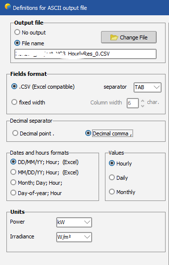
Good morning, I would think it is linked to the separator options. Double check the fields format and the decimal separator before exporting the output file and verify the format in your excel settings so that they match.
-
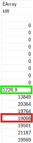
Good morning, I have created a project in PVSyst version 8.0.14 using the PVGIS meteorological file. My problem arises when I try to export the Hourly File from the project, as the data in the file is not consistent with the Report generated by PVSyst. This seems to be because in the Hourly File, some values appear without decimals (in red) while others include decimals (in green). I don't think it's a separator issue, since, as I mentioned, some values seem to be correct and consistent, but others are not. Is there any way to fix this problem?
-

Partition Definition in 3D Scene with 2-Portrait Trackers
dtarin replied to Alessia's topic in Shadings and tracking
2x28 = 4 vertical, 1 horizontal for half-cell module -
@VanoV23 Since this is a safety issue, it is important to consider the worst case and not only standard operating conditions or some compromise between. If the default definition of the worst case in PVsyst seem too conservative, they can be overridden as explained in my previous post.
-
Thank you Sir. Now it's clear. I’ll apply this logic to my system.
-
Hello Aidenn, I first notice that the power sharing has not been equalized in your print screen. All sub-arrays has the same Pnom/MPPT, though different installed PV power in each sub-array. This results in unequal Pnom ratios across the sub-arrays. You can toggle the "Auto-equal. Pnom option", or clicking on the weight icon for the specific configurations concerned. This will distribute the Pnom/MPPT values proportionally according to the installed PV power in each sub-array, thus equalizing the Pnom ratios. The production begins as soon as the MPP power is over the power threshold Pthresh of the inverter. The MPP power below this threshold is accounted as IL_Pmin loss. The Pthresh power may be understood as the power required for the Inverter internal circuits consumption. These losses might be reduced if activating the power sharing, since certain sub-arrays have rather low Pnom ratios. You can read further about in the following help pages: https://www.pvsyst.com/help/project-design/grid-connected-system-definition/inverter-array-sizing.html#difference-with-the-hourly-simulation https://www.pvsyst.com/help/physical-models-used/grid-inverter/inverter-operating-limits.html
-

Partition Definition in 3D Scene with 2-Portrait Trackers
Alessia replied to Alessia's topic in Shadings and tracking
Hi Michele, thank you again, everything is much clearer now. Just to confirm: For the 2×14 structure (a single string across two vertically stacked modules), this matches the 2TU configuration, so I’ll use 2 vertical × 1 horizontal partitions. For the 2×28 structure, with two strings (one per module row), this corresponds to the 2T configuration, so I’ll use 1 vertical × 2 horizontal partitions. That said, would subdividing further (e.g. 4 partitions in height) in the 2T case meaningfully increase accuracy, or is the standard 2‑partition approach sufficient given the partition model’s approximations? Thanks in advance. -
 OK,thanks very much!