All Activity
- Past hour
-
There is indeed an error in the Backside diffuse irradiance calculation (in some special cases) in the version 8.0.13. However this comes back to normal when you save the variant and reopent it.
-

IAM Profile Of a Module not yet in PVSyst Database
Lazare Fesnien replied to Alterna - Ingeniería's topic in Simulations
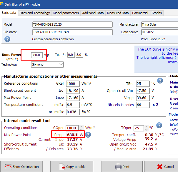
Dear Kittitut, When receiving PAN files from manufacturers, these usually define some parameters – not mentioned on the datasheets – which considerably boost the performance of their modules in the simulation. These PAN files may often be directly provided by “independent” laboratories (claimed as “certified”). PVsyst tries to detect these anomalies, and gives you this information. In these cases you are advised to use default parameters proposed by PVsyst, which are usually more realistic. There are mainly 2 classes of such uncertain parameters: The IAM profile. We are convinced that the IAM of most PV modules should follow the Fresnel’s physical laws, either for normal glass or for AR coatings. We received measurements from very serious laboratories which are very close to Fresnel. And we had still this confirmation recently after an informal discussion with a responsible of a well-known laboratory in the USA. See our FAQ https://forum.pvsyst.com/topic/1190-how-to-determine-the-iam-profile/#comment-3181 The low-light efficiency as measured by some laboratories is often biased by the fact that the filters used for the measurements at 200 and 400 W/m2 deliver slightly higher irradiance than nominal. I have analyzed many measurement reports from these labs, and observed that the Isc/G ratio is not stable, as it should be. When correcting this the low-light efficiency usually stays between -3% and -2%, rarely higher. See our FAQ https://forum.pvsyst.com/topic/1030-how-are-specified-the-pan-files-in-the-pvsyst-database/#comment-2731 When using these boosted PAN files in your simulations, you have the risk of getting over-estimated simulation results with respect to the real system.. Regards, - Today
-
Hello, I am trying to simulate a system on PVsyst where the battery storage is charged from the grid at certain times. Has this feature been added to PVSyst? if it has, how do I do this?
-
Hi, you need to enter the 3D scene and modify your PV objects to define partitions on them. Here is a help page with some guidelines on this: https://www.pvsyst.com/help/project-design/shadings/electrical-shadings-module-strings/partition-in-strings-of-modules.html
-

How is the PV system size determined?
Michele Oliosi replied to Chae Han Lee's topic in Shadings and tracking
Hi, This is an order of magnitude estimate, so we did not feel the need to be too precise. To be on the safe side: you can work with twice the distance from the center of the PV site to the edge. -

PVsyst String Configuration and Shading Scene Simulation Issues.
Muhammed Sarikaya replied to NFI's topic in Simulations
Dear NFI, I don't understand what you mean by "one way to configure the string with inverters." I invite you to watch this tutorial, which explains well how to configure it: Regarding near shading, it can indeed be difficult to place the modules. I suggest trying the zone tools as well. Also, if you encounter an error message, please send it to us at support@pvsyst.com along with a screenshot, so we can help you solve the problem. Regards, -
Yes, that is also another option, especially since you have a ready-to-use MEF file. 🙂 To address the original issue: There was an issue with the units and multipliers, which were not defined correctly. This fixed the error of the clearness index.
-
Hello, I am trying to simulate a system on PVsyst where the battery storage is charged from the grid at certain times. Has this feature been added to PVSyst?
-
 vptamara-ebi joined the community
 - Yesterday
-
 Jonwenas joined the community
 - Last week
-
 SHEYDA joined the community
 -
 Elrus9528 joined the community
 -
 Baqer joined the community
 -
 Calkir9950 joined the community
 -
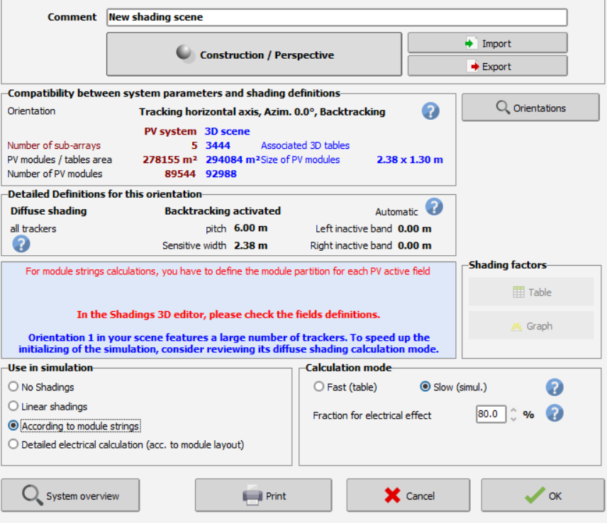
Hello, Basically I am working an large scale project , I have been asked by the Client to utilize 80 % as a value for Fraction for Electric effect , when I tried to use that factor , I got this red message ( You have to define the module partition for each PV active field ) , I dont know how to proceed , can anyone help ? after Importing the 3D Scene export from PvCase ,

-
 Fadi joined the community
 -
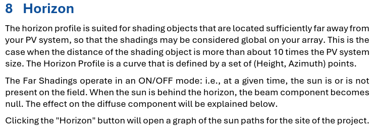
Hello, I’m trying to manually input the horizon profile, but I’m not sure what exactly "PV system size" refers to. According to the tutorial, far shading is defined as being at a distance greater than 10 times the PV system size. However, it's unclear what this "system size" means. Is it 10 times the installation footprint? Or the distance from the center of the PV site to its edge? I couldn't find any official documentation clearly explaining this, so I’d appreciate any clarification. Please excuse any awkward phrasing—I used a translator.
-
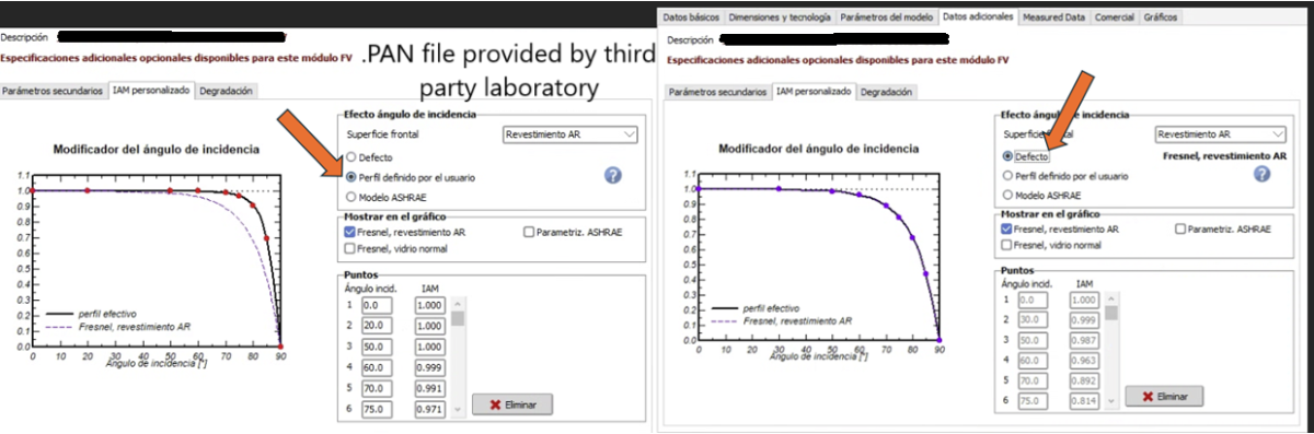
 Hello, We are working in a project where we plan to use a PV module whose data is not yet in the PVSyst database, and we are using a .PAN file provided by a third party (independent certified laboratory). There is a significant difference in generation when using the default IAM curve and the "User defined IAM profile", up to 3 percentage points. We have extensively read your post about “How to determine the IAM profile ?”, and we think the IAM profile provided has been created using outdoor measurements. Do you agree with this? Would you accept this IAM profile for a new module of the PVsyst database? Or would you consider the values differ too much? Attached to this post you can find a picture of the IAM profiles (both default, using Fresnel’s law, and "User defined IAM profile",). It’s in Spanish, sorry about that! Thank you very much for your answer!
-
Alterna - Ingeniería joined the community
-
Hi, At ANE (my company www.ane.tokyo) we developed a simple web tool to convert the data from Monsola 20 to PVsyst standard format. You can find it in the PVsyst help if you search for "NEDO" or at the following URL: https://www.ane.tokyo/NEDO-PVSYST/index.html Please feel free to contact me if you need any more help or clarification. Best regards
-
Hello, I’d like to kindly ask a few questions regarding PVsyst. We would be very grateful for your guidance and assistance. Thank you very much! When configuring the system in PVsyst, we find it difficult to adjust the string connections between the inverter and modules. Is there only one way to configure the string arrangement? Additionally, when simulating with a shading scene, is there a more efficient way to adjust the module layout? Currently, we can only roughly place the modules in their default positions. If the string configuration appears correct but the simulation still cannot be executed, how should we proceed to troubleshoot or resolve the issue?
-
 Kenbel4 joined the community
 -
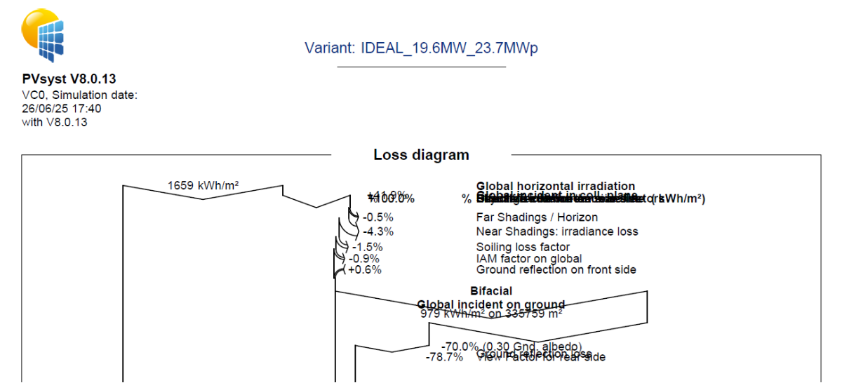
Hi PVSyst Support Team, The loss diagram in version 8.0.13 is printed with errors. Please check it. Kind regards, Carlos
-
 CarlosN joined the community
 -

Snapping objects issue (cable) - PVsyst 8
David Bourdon replied to David Bourdon's topic in Problems / Bugs
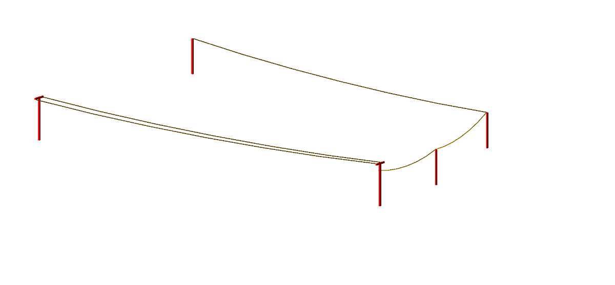
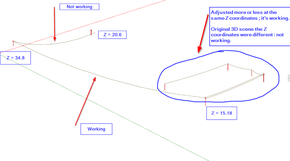
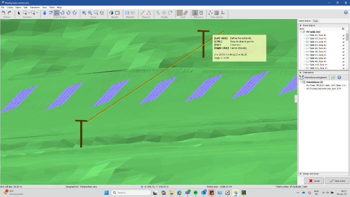
After trying several potential options to solve this I may have found a possible explanation (but not 100%). I've saved my poles as shading selected objects and started a fresh new simulation with a random meteorological file to avoid any external effect of my 3D : no effect, still not snapping. I've opened the shading selected objects in PVsyst 7.4.8 and again started a fresh new simulation : no effect, still not snapping. Then I've noticed that the snapping was working for several poles at the same altitude so I've tried changing the altitude of my other poles and then it worked with no issue. It means that depending of the altitude (I don't know what the tolerance is), the snapping function is not able to find the edge to connect the end of the cable object. 1st picture, they are more or less at the same Z coordinates ; snapping is working perfectly 2nd picture, the poles are at a different altitude, not snapping, mainly X coordinates which is affected by the poles location Now what I can't explain is that the snapping is working for another pole at a different altitude, mainly with a Y coordinates affected by the poles location... I can share a *.SHO file with my poles position and cables snapping/not snapping to help identify the issue, if necessary. Thanks for your feedback, D
-
The cable type or installation mode may affect the resistance only in terms of "Resistivity as function of the Temperature". In PVsyst, the resistivity is specified for a temperature of 50°C (alu or copper). This will be modifiable in a next version of PVsyst (probably in V 8.1). But in practice, we usually don't have any information about the cables temperature in the system during operation. NB: The resistivity variation is 0.39 %/°C. Applied to a loss which is usually of the order of 1% of the total energy, the effect is completely negligible in the simulation results.
-
Thank you for the detailed explanation regarding AC losses and the reference power selection. It's very helpful to understand how these choices impact ohmic losses. Could you please elaborate on how different cable types might affect the overall resistance and thus the ohmic losses in the system?
-
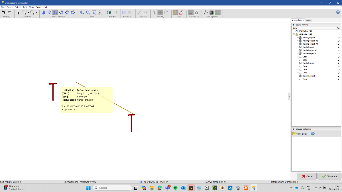
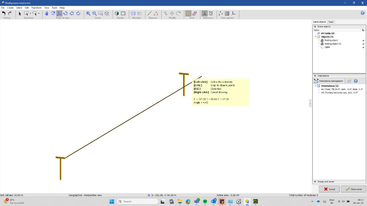
Good Morning PVsyst support and PVsyst community, I'm creating this thread as I've been struggling for several hours now trying to draw an overhead line in my 3D scene and use the snapping function (by pressing CTRL) of the cable object to connect both ends of the cable (I use PVsyst for years now, so it's not new to me and I've done it several times in the past without any issue). For some reasons, the cable object is not able to recognize the edge of my second shading object to connect. I've tried several type of shading objects to see if it makes a difference but so far still not working (parallelepiped, composed object from parallelepiped, electric pylon) The start point is never a problem but the end point is never found and can't connect to my second shading object. I've tried to remove the other objects from my 3D scene such as topography, ground image, even the modules and keeping only the two "pylones" that I want to connect but it's not changing anything. I'm using PVsyst 8.0.13 and tried as well with 8.0.12, but same effect. If I place my cursor where I want to connect the end of the cursor and then press CTRL, the end point moves to another location with nothing visible. I've tried to manually place the cable between the poles but moving in 3D it's almost impossible to do something clean. If I start a fresh new 3D scene for the same project and try to create basic parallelepiped and connect the cables it works... If you have any idea or advise to solve this... Thanks in advance ! Best regards
-
 Greetings PVsyst team. I'm working with a PV system with bifacial and monofacial modules. I've already created differents orientations for each sub-array, but now I wonder how PVsyst consideres theses two kind of modules on simulation. There is any other parameter I should keep my eye on it? In future versions, would be possible to set degradations per sub-array?
 -
The number of rows is only used for the bifacial calculation for the backside irradiance, where the simplified 2D cross section view is needed. For the front side, the electrical shading is fully simulated as defined in the 3D scene.
-
That makes sense, but if partitions are defined to account for the electrical effect, wouldn't this approach ignore edge effects and the N-S space between tracker tables?
-
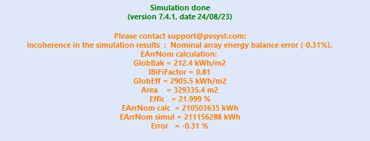
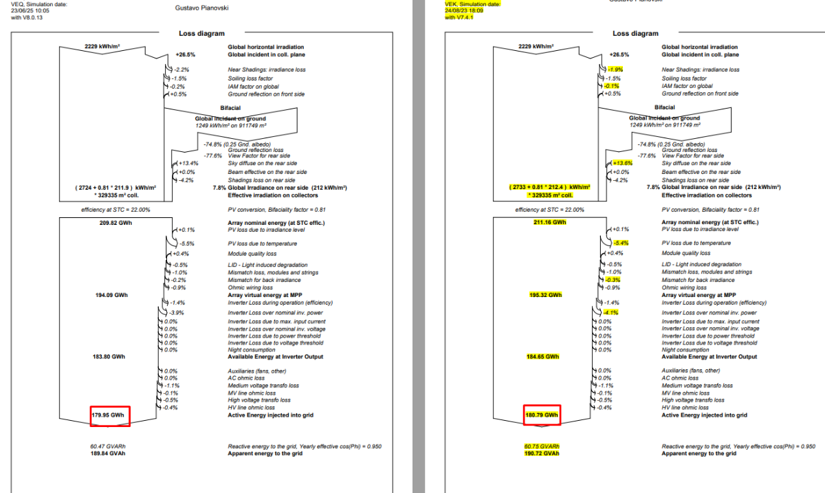
This warning has nothing to do with the Pmpp difference between the nameplate and the one-diode model result. This is due to a problem in the simulation process (irradiance calculations), which has been corrected in the V 8.0. But sorry, I can't say anything more without analysing your project in detail.
-
Dear Michele, I am working on a V7.4.1 project to extract the some variable, and the following warning appears: I analyzed the .PAN and the difference observed is 0.01%. However, the difference in E_Grid is 0.46%, of which 0.3% is due to Near Shadings losses: In the simulation using Version 8.0.13, this problem does not appear. Does simply performing a new simulation in Version 8.0.13 solve this problem? What are the reasons for this warning? What updates have been implemented to fix this bug?
-
The number of rows refers to the number of rows in the 2D cross-sectional representation of the system, assuming "unlimited long tables", and is relevant for the calculation of the effect of the first and last row of the array. In your case it would rather correspond to 38 rows, imagining the view in 2D. Number of sheds (rows) and accuracy - PVsyst documentation
- Earlier
-
PVsyst is a worldwide distributed software. We obviously cannot include such national or local requirements, especially like this one which seems to be very evolutive. Moreover, we don’t want to take any responsibilities regarding such national administrative rules.