All Activity
- Past hour
-
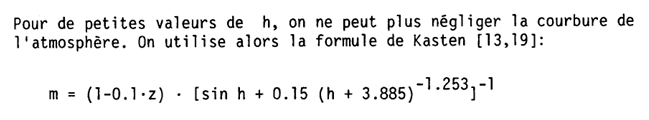
 Dear Zaki We do not cap negative values in the Perrez model when computing the circumsolar brightness. They arise when implementing the model and we keep them to avoid biasing the result towards positive values. This term is added to the isotropic component and the irradiance itself is never negative. The horizon is not implemented as a band. The horizon component is calculated using the Perez/Ineichen's 1990 model, but it is directly added to the diffuse irradiance. Horizion shadings are applied as a fraction on the diffuse irradiance but not to the horizon irradiance component separately. For the air mass, we use the the Kasten model described in Ineichen's thesis "Mesures d'ensoleillement à Genève", which is corrected for altitude as well (exp(-0.00013*altitude)) https://unige.swisscovery.slsp.ch/discovery/fulldisplay?vid=41SLSP_UGE%3AVU1&search_scope=MyInst_and_CI&tab=41SLSP_UGE_MyInst_CI&docid=alma991006463789705502&lang=fr&context=L&adaptor=Local Search Engine&query=sub%2Cexact%2CKANTON GENF (SCHWEIZ)%2CAND&mode=advanced&offset=0 I hope this helps you in your study
-
 It depends on the layout of the strings in the field. We don't have a rule of thumb, but you could do something along these lines: you can make some simple assumptions concerning your field. For example, if your trackers are 2P (two in portrait), then you could assume that there are two strings per tracker, i.e. 1529 strings total. Then you could also assume that the trackers are roughly arranged in a square terrain, with GCR 0.4. And that modules are 1x2 m^2. Let's say x is the number of trackers on a single line along the axis and y is the number of rows. Roughly, y * 2 (# modules in table height) * 2m (module height) / 0.4 (GCR) = 24 (# modules in table length) * x * 1m (module width), i.e., y = 2.4 x. The total number of trackers is 1529 = y * x = 2.4 * x^2. Solving, that you get roughly x ~ 25 and y ~ 60. So 60 rows should be roughly it. Note that above 10-20 rows, the impact of the number of rows becomes quite small, so for systems of this size the exact values are not important at all.
 - Today
-
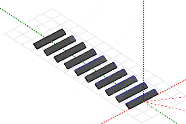
Partition Definition in 3D Scene with 2-Portrait Trackers
Michele Oliosi replied to Alessia's topic in Shadings and tracking
We have calibrated the number of partitions based on the module layout calculation. Therefore, all these effects are taken into account in the partition model. The partition model per se is an approximation that will not always reflect the details of the electrical effect of partial shadings, but that should recover a plausible loss value for a long term (e.g. a year) simulation. However, for the case of the 2x14 structure, it should not be a partition that traces through the middle of the modules. That would be correct for the case 2T. Instead, this 2x14 structure is in the case 2TU, which has two partitions with size 1x14. -
 I am currently working with PVsyst version 7.4. Thank you for your response. In my case, I only have the total number of strings and the number of modules in series per string. Could you please guide me on how to calculate or estimate the appropriate number of sheds from this information? Is there a rule of thumb or a formula to follow based on the electrical layout (e.g. 24 modules per string, 3058 strings in total)? I would like to make sure that the "Number of sheds" I enter corresponds realistically to the physical arrangement of the system in the field. Best regards, Laila Raouane
 -

Partition Definition in 3D Scene with 2-Portrait Trackers
Alessia replied to Alessia's topic in Shadings and tracking
Thank you Michele. To make sure I fully understand the implications for my specific case: Since the modules are connected in series (one string per 2x14 structure), shading on the bottom module would affect the performance of the top module as well, even though the top one remains unshaded. If I simply divide top and bottom modules each into two partitions (totaling 4 vertical submodule partitions per string), I am concerned this may miss the fact that shading on the bottom module electrically impacts the top module through the series string connection. How would you recommend managing this configuration? Thanks again. -
Hi ! Which version are you using? I am asking this because in the current version this is not stated, as far as I know. The unlimited orientations do always include mutual shadings. The shadings calculation is inherent and is not related to choices in the "Near shadings" window. The number of rows (with the frenchism "sheds") is actually quite important for the evaluation of mutual shadings: it does affect simulation results.
-
Partition Definition in 3D Scene with 2-Portrait Trackers
Michele Oliosi replied to Alessia's topic in Shadings and tracking
Hi ! Yes, in general it is necessary to define partitions whenever you want to perform electrical shading calculations using the option "according to module strings". However, if you use the mode "Module layout" then the partitioning is not necessay as the submodule and structure is defined in the PAN file. No, in general the partitioning is not = to 1 string, sometimes you should count several partitions per string. For example, the half-cell parallel structure usually means doubling the number of partitions. You can find various examples here: https://www.pvsyst.com/help/project-design/shadings/electrical-shadings-module-strings/partition-in-strings-of-modules.html. Your cases are the 2TU and 2T respectively. -
Dear PVsyst team, In the Orientation → Unlimited sheds section, it's mentioned that the "Number of sheds" is only for visualization and does not affect simulation results. However, I noticed that changing this number (e.g. from 5 to 12) slightly alters the energy yield and PR, even when mutual shading is disabled and all other parameters (pitch, tilt, GCR, etc.) stay the same. Could you please clarify: How should we choose or calculate the number of sheds? Why does it impact the results if it's only for display? Could internal parameters (like edge effects or area estimation) be influenced? Thanks in advance for your help. Best regards, Raouane Laila
-
RAOUANE LAILA joined the community
-
Dear PVsyst Team, I’m reaching out to ask for your support regarding a 3D scene I’m simulating using trackers in a 2-portrait configuration. In this model, I’m defining the partition on two types of trackers: One with 2×14 modules, corresponding to a single string. Another with 2×28 modules, corresponding to two strings (one on the top row and one on the bottom row of the structure). I have two main questions: In general, is it necessary to define the partition if the module is already specified as a twin half-cell with 3 submodules in the PAN file? If so, how should the partition be configured? In my specific case, where there is only one string per structure, the partition would logically be 1×1. However, if a partition is still required due to the module’s half-cell architecture (as per question 1), how should I define it in this scenario? Thanks.
-
 Halmilo4335 joined the community
 -
 DiegoNav joined the community
 -
 achmad subayu joined the community
 - Yesterday
-
 Marklian27 joined the community
 -
 Yvano joined the community
 -
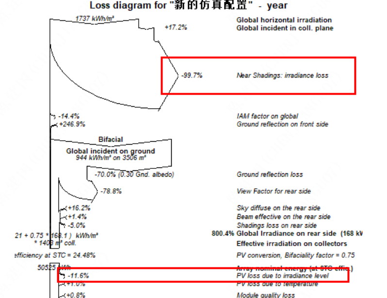
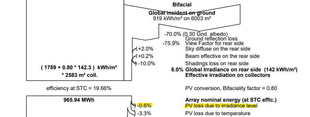
Hello ! This is normal. Since there is very little irradiance as a total on the PV cells, the efficiency derate is on the low end of the curve that Luca showed. You also must take into account that the loss diagram is an average over many irradiance conditions (probably ranging between 0 and 200 W/m^2). Once you put everything together, the average loss of efficiency may well be 11% (below what you would get by just examining the loss of efficiency at (21 + 0.75*168.1) W/m^2.
-
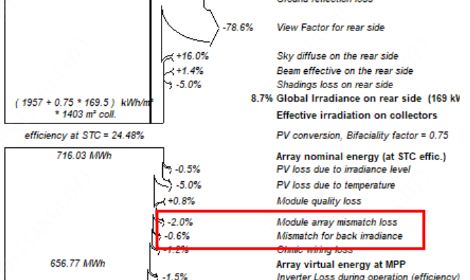
 Dear sir: Can you take a look at this problem? Why is the backside mismatch loss calculated separately from the front side, rather than being added to the front side like irradiation. thanks!
-
When I completely shade the front side of the module and allowed the back side to receive light, I found that the loss due to weak light was relatively high.
- Last week
-
 Tazed6914 joined the community
 -
 xegige1348 joined the community
 -
this is also happening. all after update .14
-
Hi all, my colleagues and i are having errors when printing reports in the newest update. .14. the reports are either blank or the loss diagram is jumbled.
-
 Hi PVsyst Team, I’m a PV Performance Engineer at TotalEnergies, We’re currently performing a detailed performance comparison using PVsyst, PVlib and SAM, for one of our large-scale PV clients, using the same high-resolution meteorological data derived from on-site field measurements. We’ve noticed areas where PVsyst’s POA outputs differ, and we’d love your insight so we can explain the differences: Negative circumsolar term values Around sunrise/sunset and significant differences in Isotropic diffuse too. Most Perez (1990) implementations cap that at zero (in PVlib, SAM). whether this is intentional, and if so, why PVsyst retains negative values rather than forcing them to zero. Is PVsyst’s Horizon brightness implemented as a band? numbers diverge from SAM and PVlib’s continuous-integration approach. Any guidance on how that band or weighting is defined would help us reconcile the three software outputs. do you use other air‐mass equation when computing? because in PVlib defaults is to the Kasten & Young (1989) air mass formula, which can shift the sky brightness attenuation and thus POA irradiance calculations. Understanding these points will allow us to prepare a clear, defensible comparison report for our client highlighting not just “which software” but why small differences arise at low sun angles or under certain horizon conditions. Thank you in advance for any details or references you can provide. Best regards, Zaki B.
 -
Zaki BOULAOUCHE joined the community
-
OK,Thank you for your detailed answer.
-
Hi Bruno, You wrote: "It could happen that the DC is connected at a time when there is already a significant irradiance, but the ambient temperature is still low." But when the system is operating even at low temperatures, is there really a point in calculating the Voc voltage? In my opinion, at that stage the system is already in operating mode, so the voltage should be calculated based on Vmp, not under open-circuit conditions. That is, Voc can only be critical during system startup, and if the irradiance level is low, the system will transition into operating mode and everything will work properly. Am I right in thinking that considering only the worst-case scenario is not always the best approach, and that it's important to find a compromise?
-
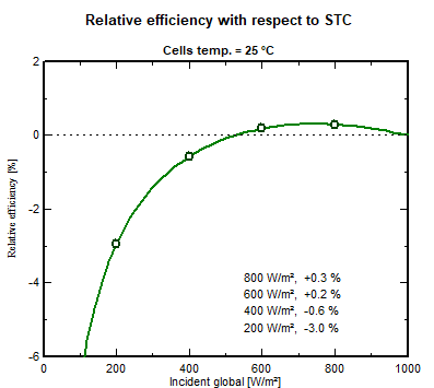
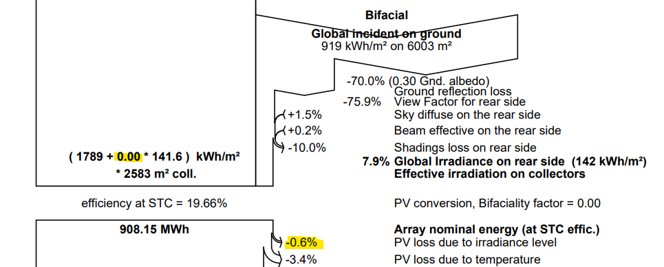
 Careful, the 200W/m2 I indicated was not refering to the rear side irradiance. It was a lower irradiance level, irrespective of whether the front or the rear recieves it. I would agree with your calculation only in the case where the front side doesn't recieves any light. Otherwise you cannot decompose the efficiency in two parts from front and rear, it doesn't add up linearly. You need to consider the full I-V curve under the effective irradiance of both front and read sides together. ----- Let's take other numbers to not create confusion again. If in certain scenario, the front side recieves 1000 W/m2 and the rear side e.g. 50W/m2, the module recieves an equivalent of 1000 + f*50 W/m2 of total irradiance. Let's say f=0.8, it is 1040W/m2. If the irradiance level is lower, let's say 5 times lower, the front side recieves 200 W/m2 and the rear side 10 W/m2. Thereforer, under low light, the module recieves an equivalent of 208 W/m2 in total. The curve of performance of the module as function of irradiance should be understood as function of this effective total irradiance. (Indeed, in the norms, when bifacial module are measured, the rear side is masked to not absorbed any light from the rear.) You can visualize this curve in the .PAN file: So whether the light comes from the rear or the front, it is the Incident global light that matters. For this specific curve, if the Incident global Incident global = front-side irradiance + (rear-side irradiance × bifaciality factor) is equal to 200 W/m2, the efficiency will be -3.0% lower than if the Incident global was 1000 W/m2. So any module PV module, bifacial or not, under given illumination condition will operate somewhere on this curve. If the module operates above the reference of 1000 W/m2, you have an efficiency degradation with respect to STC, between 500-1000 W/m2 (for this particular example), you have an efficiency boost, below 500 W/m2 you have an efficiency degradation. It doesn't matter if it is bifacial or not. However, the bifaciality has this influence that the module will operate at a higher illumination level than a monofacial counterpart (in the hypothesis they have exactly the same electrical properties), so at another position on this curve. But as you can see, it could well either mean an improved performance! PVsyst of course take this into account during simulation and you can find it in the loss diagram. For example if you use the "Demo Commercial Oakland" with VC6, you can see it there If for the sake of the test, you modify the .PAN file and set the bificiality factor to 0, you get then: Therefore, for this specific example, on the yearly production you don't see a specific loss difference due to the irradiance level operating further from STC between a bifacial and monofacial module. This is because this effect is small here (I would call it a third order correction). If you had a system with better Albedo for example, the comparison could be different.
-
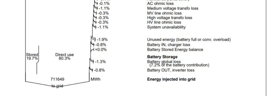
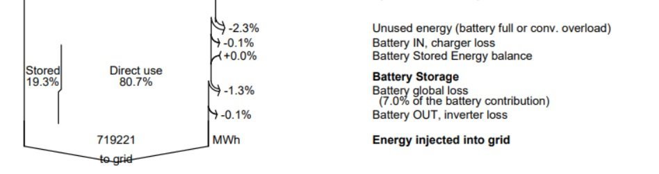
Why the battery stored % value increases when I decrease the efficiency of the converter and the inverter to 97% from 100%. 19.7% stored is with default converter and inverter parameters of efficiency. -0.8% loss of Battery IN & Battery OUT. Photo attached. 19.3% stored is with increasing the hypothetic converter and inverter parameters of efficiency to 100%. -0.1% loss of Battery IN & Battery OUT. Photo attached.
-
ok,I agree with your viewpoint, but do you think this calculation is reasonable? if the fornt side of module receive irradiance of 1000 W/m², and the rear side of module receive irradiance of 200 W/m², front side:(f × 22- f × 22) / (f × 22) = 0% (relative) rear side:(f × 21.34 - f × 22) / (f × 22) = -3% (relative)
-
Currently, the only way to import sub-hourly data in PVsyst is to use the "custom file" import format. https://www.pvsyst.com/help/meteo-database/import-meteo-data/custom-meteo-files/index.html
-
Sigma Shifts for Gaussian Distribution Information
Auriane Canesse replied to rjv7888's topic in Simulations
The formula you have been applying is for a 2-sided test (~chances that the result is different, larger or smaller) whereas in this case a 1-sided test is appropriate (~chances the result is larger only) https://en.wikipedia.org/wiki/One-_and_two-tailed_tests -
norm.inv(Pxx,0,1). P99 is 2.33, not 2.35
-
Clarifying Definitions to Avoid Confusion At PVsyst, the term "low-light performance" is usualy defined in the context of a PV module illuminated solely from the front side. Let’s consider the following example: At a reference irradiance of 1000 W/m², the module has an efficiency of 22% At a lower irradiance of 200 W/m², the efficiency drops slightly to 21.34% We define low-light performance as the relative difference in efficiency: (21.34 - 22) / 22 × 100 = -3% (relative) This means the efficiency at the lower light level is 3% lower relative to that at full irradiance. This is the standard definition used in PVsyst. Important Note: A more negative number (e.g., -4%rel or -5%rel) does not necessarily imply worse performance. In fact, it often indicates that the module performs better at high irradiance (1000 W/m²), which is an observed trend in modern PV modules, largely due to reduced series resistance Bifacial Modules and Rear-Side Illumination When it comes to bifacial modules, if only the rear side is illuminated (for the sake of the discussion), the module’s efficiency is proportional to the front-side efficiency, scaled by the bifaciality factor f. This factor applies equally at both high and low light levels. Therefore, the relative low-light performance of the rear side is identical: (f × 21.34 - f × 22) / (f × 22) = -3% (relative) Link to the Bifaciality Factor Definition To relate this to my colleague’s earlier explanation: the bifaciality factor is defined as the ratio of power output when the module is illuminated from the rear versus the front. This difference in power is primarily due to optical property differences between the two sides of the solar cell. Indeed: The cell materials are different on the front and rear sides Any differences in charge transport or extraction are negligible (These effects are much much smaller than the typical uncertainty in datasheet bifaciality (e.g., 80% ± 5%)) Thus, the bifaciality factor can effectively be understood as a scaling factor for the photogenerated current. In practical terms, the total irradiance received by a bifacial module can be calculated as: Irrad_Tot = front-side irradiance + (rear-side irradiance × bifaciality factor) The PV module performance modeling can then proceed without needing to differentiate which side the light is coming from—the model is agnostic to the direction of light incidence and so is the low-light performance.
- Earlier
-
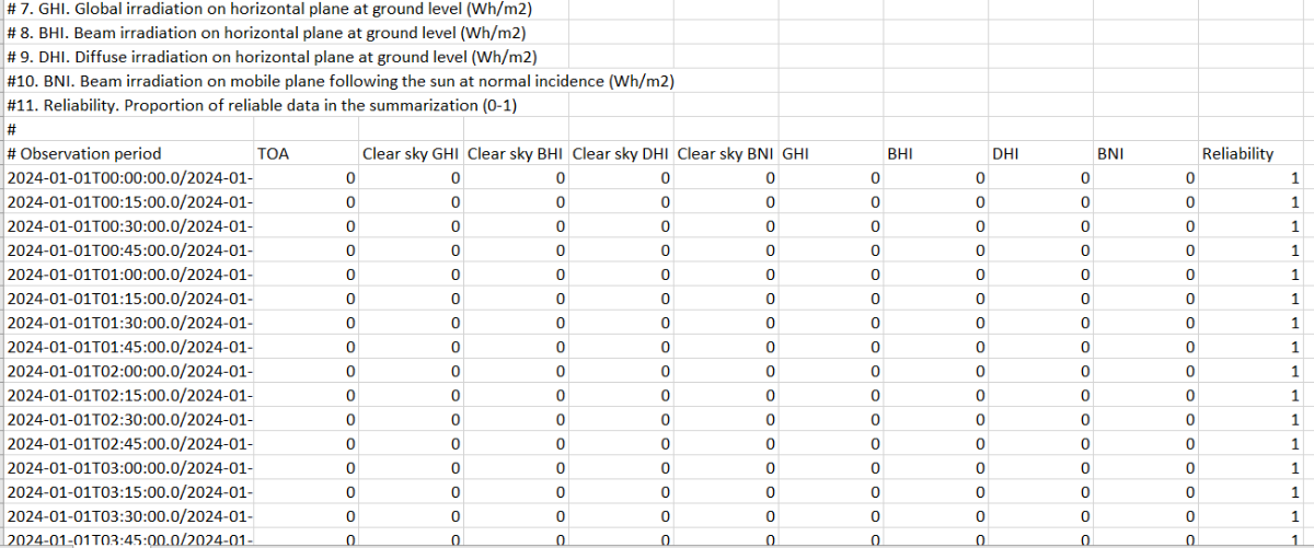
Hi everyone! I would like to upload meteo data obtained from CAMS radiation service - SoDa. Particularly in intervals of 15 minutes, ¿is it possible or PVSyst just accepts above hourly registers? I also noticed that the information comes this way: Not any register about temperature. According to your post Meteo Database > Import meteo data > PVsyst standard format, that would be necessary so, in this case, how could I proceed? I only have GHI and DHI Thanks in advance. Óscar