All Activity
- Past hour
-

Citing the Hay Transposition Model in the PVsyst References
Michele Oliosi replied to kjs55's topic in Suggestions
Funny, I just added this in the help of our 8.1 candidate a few days ago. Hence sure, will be present in 8.1 🙂 Indeed, that is the correct citation. - Today
-
Hi, I conducted a study on hourly values for a solar power plant (SPP). I compared two different meteorological data sources. Meteonorm shows higher production in the morning than PVGIS, while PVGIS shows higher production in the afternoon than Meteonorm. Why are the production values different? Meteonorm (kW) PVGIS(kW)

-
 Emre Sagir joined the community
 - Yesterday
-
Could you please add the formal citation for the Hay transposition model to the PVsyst Help References? It would be very helpful to have the primary source explicitly listed alongside the other physical models at these locations: V7: https://www.pvsyst.com/help-pvsyst7/index.html?references.htm V8: https://www.pvsyst.com/help/references.html My assumption is that it is the following citation (IEEE format): J. E. Hay and J. A. Davies, "Calculations of the solar radiation incident on an inclined surface," in Proc. 1st Canadian Solar Radiation Data Workshop, 1980, pp. 59–72.
-
You can download time-series data (20+ years) from https://nsrdb.nrel.gov/data-viewer. From there you can calculate it manually from GHI or import each year into PVsyst. You can also get ~18 years of data at PVGIS free https://re.jrc.ec.europa.eu/pvg_tools/en/#MR.
-
This tool is meant to compare .MET files, you first need to create several .MET files using different data sources
- Last week
-
Hi, I tried with the second link to stimate a location but I coul not get an output. What should I do?
-

Bifacial Performance Ratio Formula in PVsyst V7 Help Menu
Auriane Canesse replied to kjs55's topic in Suggestions
Thank you for the report. Note that this bug was corrected in PVsyst 7.2.17 https://www.pvsyst.com/help/release-notes/index.html#exec-1--version-7217 -

No view for the report only black screen
Hizir Apaydin replied to Petr Pasek's topic in Problems / Bugs
Dear Petr, The problem seems to be related to a driver issue. You can try to update this driver by following the procedure documented in our FAQ: https://forum.pvsyst.com/topic/1253-updating-your-graphics-card-driver-pvsyst-660-and-above Alternatively, you can follow the procedure linked below: https://nvidia.custhelp.com/app/answers/detail/a_id/5035/~/run-with-graphics-processor-missing-from-context-menu%3A-change-in-process-of In order to try to run PVsyst with the second graphic card driver of your PC (if you have one). This selection is available in Windows settings (in Graphics settings) after you have chosen PVsyst program file: https://desk.zoho.eu/galleryDocuments/edbsn7903bf68f74bdf02e267dfb94ecb7a844a3b3dfe543b433eda69af27a6de02cfce10a448941bc47fa2fd77e1e764447e75de7024769cf0298f804ff62b2e141f?inline=true If you use a virtual machine (VMWare, VirtualBox, ...), remember to activate hardware acceleration and be up to date. If you are using the AMD “Adrenalin Edition”, please try using another driver using this procedure: https://www.youtube.com/watch?v=O94izh6mwOk We remain at your disposal for any other assistance that may be required. -
 Shailja Sadhu joined the community
 -
 nurul joined the community
 -
 wepedsonic7 joined the community
 -
Please help with the problem of generating a preview for a report. I don't know what else to try. Thx
-
 Petr Pasek joined the community
 -
PVsyst V7.2.16: PVsyst V7’s Help Menu (https://www.pvsyst.com/help-pvsyst7/index.html?performance_ratio.htm) defines the bifacial PR as PRbifi = PR / (1 + (GlobBak + BackShd)/GlobInc), i.e., adding BackShd to GlobBak. In my V7.2.16 run, the reported PRbifi aligns only when BackShd is effectively subtracted, which points to a doc/implementation mismatch in the V7 build.
-

Albedo shading component calculation
Linda Thoren replied to ClaireWest's topic in Shadings and tracking
The albedo shading loss will be the same. But with all the parameters set for a bifacial system the variable "ground reflection on front side" is added for the inter-row ground reflection, as described in the help page. For a monofacial system, the irradiance that falls between the rows is not calculated and the contribution of the ground reflection on front side is in general negligible for systems with a low tilt angle. To evaluate this gain, at the moment you need to set the bifacial parameters as described above. -
 Maitha S joined the community
 -
 Mbelli Njah Fongha joined the community
 -
 kidsbikes34 joined the community
 -

Albedo shading component calculation
ClaireWest replied to ClaireWest's topic in Shadings and tracking
Are you saying that the (front-side) near shading loss would be lower if i modelled a bifacial system because these systems are more precisely modelled or defined, even though the near shading losses happen before any bifacial modelling in the loss diagram (and should be independent of whether the system is mono or bifacial)? -
 piterpal1988 joined the community
 -
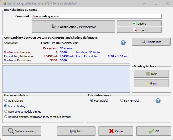
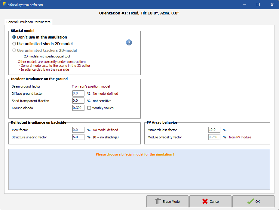
Hi, The bifacial model presently available in PVsyst is based on a simplified 2-dimensional representation, with similar assumptions as the "unlimited sheds" or “unlimited Trackers” PVsyst simplified calculation. This approximate calculation may be extended to a 3D scene, provided that this 3D scene is sufficiently well represented by the "Unlimited sheds or trackers". Thus, simply use the option "Use unlimited sheds 2D-model" in your second print screen. You find a tutorial about the bifacial model conditions for the 3D scene below:
- Earlier
-
Dear PVSyst Team, I am currently trying to simulate a bifacial system in the PV System configuration. However, when I open the Bifacial System settings, the 3D shading scene does not appear to be connected to the bifacial configuration. In the 3D Shading section, I have already created and added the 3D shading scene. However, it is still not recognized in the Bifacial System window. Could you please assist me in resolving this issue? Is there any step that I might have missed which causes the 3D shading scene not to appear in the bifacial system settings? For your reference, I have attached screenshots of both the Near Shading and Bifacial System sections. Thank you for your support.
-
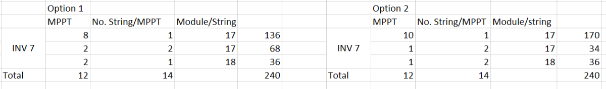
From your table, I understand you have in one case 2*2 MPPT with 2 strings each, and on the other one only 2 MPPT with 2 strings each, is that correct ? You may or may not see any difference in your results depending on how you've set your simulation parameters. Having two strings per MPPT may result in a lower production when : The combined strings power or current exceed the MPPT limits. The voltage mismatch value in the detailed losses in not null. Please also note that the maximum MPPT power depends on the power sharing option. If you have unbalanced MPPT input power, you can redistribute the total inverter power accordingly. This will let the MPPT connected to two strings to have a higher power limit, and strongly reduce the difference between your two configurations
-
Hi this is still not possible. It is still as @dtarin commented.
-
Albedo shading component calculation
Linda Thoren replied to ClaireWest's topic in Shadings and tracking
Hi, Indeed, today the ground reflection between rows is only considered for bifacial systems. In general, this contribution is very low with sheds and trackers systems, but becomes more important with high tilts and large pitch and crucial with vertical East-West bifacial systems. The calculation of the ground reflection of the front side involves an accurate definition of the ground, its albedo, the geometry, and the full calculation of the ground points view factors. So, the ground reflection of the front side is considered for bifacial systems since all of the needed parameters are already defined, but neglected for monofacial systems. The only way to run a simulation including the ground reflection for the front side for a monofacial system today, would be to alter the PAN file (activating the bifaciality and put the bifaciality factor to 0) and run a simulation with the bifacial parameters, though everything except the ground reflection on front side will be 0 given the bifaciality factor of 0. In the following help page, the reflection on the ground is further discussed: https://www.pvsyst.com/help/project-design/bifacial-systems/bifacial-systems-results.html -
Hi @Michele Oliosi, I, too, am looking for the individual inverter-level output data from the 8760. My system has 9 inverters. So, is it possible to get the individual inverter level generation data for each of the 9 inverters in separate columns after PVsyst simulation in the 8760 directly? Could you please guide me on this? Hi @solarDG1470, Did you figure out a way for this? Does PVsyst provide this data or is there some other way around? I would really appreciate it if you could share your knowledge on this. Thanks!
-
Hello, The far albedo in the project settings, will be considered in all projects and correspond to the albedo of the surrounding of the project. The albedo in the bifacial system window is indeed only set for bifacial systems and correspond the the albedo of the ground just underneath the modules. This is not necessarily the same as the far albedo of the surrounding. Kind regards
-
Hi everyone, I have a concern: will the simulation results be different with different configurations like below picture? I think it's yes in practical but in simulation, it shows not anymore different. Could anyone help me to understand this, please? Let's assume the model being used is SG125CX-P2
-
Albedo shading component calculation
ClaireWest replied to ClaireWest's topic in Shadings and tracking
Sorry, the albedo shading factor should be *~65% and *~48% during these times, not sure what happened there -
Performance model IEC TS 61724-2 and IEC TS 61724-3
Michele Oliosi replied to cloudwalker's topic in Simulations
Hi, It's definitely possible. Currently the prerequisites for the EPI test are not very strict. It is about comparing total expected energies with measured ones, filtering for various contexts, with an hourly aggregation of measurements. PVsyst will generate a time series of results with various intermediate variables, that can help with filtering (e.g. for constrained periods). This time series can easily be compared with the measured one. For capacity testing (PPI), depending on the version of the standard -2, ed. 1 or 2, it is more or less easy to do. Ed. 1 should be straightforward. Ed. 2 has minute simulation as a prerequisite. Currently, PVsystCLI or PVsyst + batch can help implement a batch of 60 simulations (one for each minute in the hour) to mimic a minute-resolution simulation. This is a bit cumbersome, though. Luckily, we are working on PVsyst 8.1 which will simulate in minutes as well. The version is well underway (and the minute simulation is confirmed to work). This will make the ed. 2 capacity test straightforward as well. -

Generating an output file for later years using the aging tool.
Tonderai replied to Tonderai's topic in Simulations
Thanks dtarin, it worked! -
You can find more information here: https://www.pvsyst.com/help/physical-models-used/pv-module-standard-one-diode-model/pvmodule-structure/bi-facial-modules.html
-
 Dear PVsyst Team, I would appreciate your clarification regarding the definition and use of the Albedo parameter in PVsyst. In the software, the Albedo value appears in two different locations: Project Settings → Site → Albedo System → Bifacial System → Albedo Could you please clarify: What is the functional difference between these two Albedo inputs? In bifacial simulations, should both values always be identical for consistency? kind regards, Irakli