All Activity
- Past hour
-

Does Far Shading Impact Near Shading Losses?
Linda Thoren replied to Chae Han Lee's topic in Shadings and tracking
Hello, In general, far shading affects the entire PV field uniformly — at any given moment, the sun is or is not visible on the field. As a result, it can potentially reduce the impact of near shading, since far shading may occur during times when near shading would otherwise be present, typically when the sun is low on the horizon. -
Hello ! Regarding the snow data, actually the snow depth time series data is not used by the simulation in PVsyst. Instead, the impact of snow is present via the albedo factor (monthly). Typically, if snow is present on the ground, the albedo factor is between 0.4 and 0.8. You could check how many days are snowy in a given month, and proportionally increase the albedo. For the warning on the clearness data, we would need to take a look at the data. Can you send the data and MEF file to support@pvsyst.com? Else, you can share a screenshot of "Best clear days Ktcs" graph and "Monthly best clear days"? That will also help.
- Today
-
 Dear S. Oviedo, Please email us your PVsyst LOG files (using menu <File> <Export logs>) at: support@pvsyst.com so we can analyze what happened and try to reproduce the issue you reported. Best regards.
 -
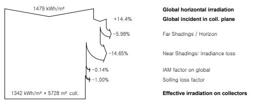
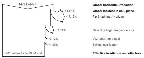
Dear PVsyst Support Team, I’ve encountered an unexpected behavior in the simulation results. I applied different Far Sahding horizon profiles to the same project, while keeping the Near Shading scene exactly the same. However, I noticed that the Near Shadings losses changed depending on the Far Shading configuration. Could you please clarify: Does the Far Shading (horizon line) influence the calculation of Near Shading losses? If so, is this due to how diffuse or albedo components are modeled in the Near Shading algorithm? Are there known changes in this behavior across different versions? I would like to ensure that my simulations reflect shading losses accurately without unintended overlaps or misinterpretation. Thank you for your support.

- Yesterday
-
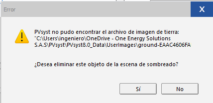
 Greetings 😁 As mentioned, I've done a licence transfer from one pc to another (Did a clean format and decided to switch). After (correctly?) selecting the desired workspace folder (Same as always, it's in Onedrive's cloud), PVsyst finished installing and almost everything works fine, projects show up, reports, etc. The issue is, when opening 3D scenes which had ground images before, they wont show up. ("PVsyst couldn't find the ground image file: .... Do you wish to delete this object from the shading scene?") Sorry it's in spanish Ground image file is still being searched in the previous pc directory. It just looks in an unexisting directory. Is there a workaround for this? Anything I can try? Thanks in advance,
-
S. Oviedo. joined the community
-
 Bipin joined the community
 -
 Mark Russell joined the community
 -
 Paul Gaudry joined the community
 -
 Hussain Hamid joined the community
 -
 Leowen346 joined the community
 - Last week
-
Incidentally, it is possible to upload the original METPV-20 data (public data), the data formatted for loading into PVsyst, and the MEF file used to load into PVsyst. Could you give me any useful recommendations from these?
-
-
It was easy to organize the METPV-20 data and import it into PVsyst, but I keep getting a warning that the clarity index is too low compared to the clear-sky model. I haven't yet made use of the Best clear days Ktcs graph.
-
Good morning. I have been involved in the development of solar power plants in Japan for over 15 years. I have recently been operating a small bifacial vertical solar power plant in Hokkaido, a snowy region, and have experienced the snow albedo effect. So I am continuing trials to incorporate NEDO's METPV-20, which also includes snow depth data, into PVsyst. Has anyone been successful?
-
 Osamu joined the community
 -

Is there a way to adding load profile for each month?
Suphanat replied to Suphanat's topic in Simulations
So I have to work the profile as .CSV File If I want to seperate the profile for all month right? That's fine then, Thank you very much! -
Is there a way to adding load profile for each month?
Linda Thoren replied to Suphanat's topic in Simulations
With the option "Load values from a CSV hourly file" you have full liberty to define the load profile exactly how you wish. -
Is there a way to adding load profile for each month?
Suphanat replied to Suphanat's topic in Simulations
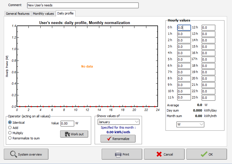
Do I have to used Monthly normalizations in order to input the daily hourly profile for every month? Seems like they still using the same Load Profile and change the values for each month based on how many days in the month. I want to input the profile for every month without them connecting like this.
-
Is there a way to adding load profile for each month?
Linda Thoren replied to Suphanat's topic in Simulations
Hello, In the version 8.0.13 we corrected a bug and a daily hourly profile is now normalized and saved properly. You also have the possibility to import a .csv file with hourly values for the full year. The different ways of defining a self-consumption profile are further described in this youtube tutorial: -
Hi there. I have many projects that require me to use PVsyst to simulate PV systems. In some cases, I also need to add the consumer's load profile. Every time I do this, I have to use the Seasonal modulation feature, where I group the load profiles by sets of months in order to input the data. Is there a way to add a daily load profile with hourly values for each individual month? I tried using Monthly normalizations, but it ended up applying just a single profile to all months.
-

how to simulate the back-contact solar cell module performance?
Jakson replied to Chen's topic in Shadings and tracking
To simulate how the panel will perform, you’ll need to use specialized software like PVsyst, PC1D, or COMSOL. These tools help you understand how much electricity the solar panel can produce under different conditions. -
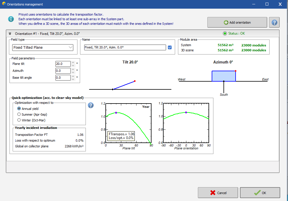
The global irradiance in the plane of the array (GlobInc)depends on the tilt and azimuth of your system. In general, one would choose an orientation of the panels in a way that maximizes this irradiance, which is why the GlobInc is usually higher than the irradiance on a horizontal plane. When defining a fix tilted plane, you find a "quick optimization tool", illustrating in an order of magnitude what you could expect to gain (or lose) compared to a horizontal configuration at your site.
-
This is a good remark, it will be useful for many users. In principle, we do recommend trying to group orientations into fewer average orientations. Usually, orientations should fall into an average whenever there are identical nominal orientations (for example, despite the irregularities caused by a complex terrain), or when they fall into the same DC array, which will facilitate the “System” window definitions. When there are notable differences, such as different ground types, backtracking parameters, types of racking, etc. it may be worth keeping separate orientations, of course. This will facilitate definitions. For example, if there are different ground types, determining albedo values for each of them makes sense. However, the default behavior when importing a 3D drawing is not fully in tune with these recommendations, yet. Indeed, by default, the 3D import will separate orientations based on effective angles. Therefore, a necessary step is to regroup orientations. The simplest way is to select all concerned PV tables in the 3D scene, and then use the right-click menu to create an orientation from the selection. Any other method works here, as long as it allows for an educated grouping of orientations. We are looking into improving this default behavior at the stage of 3D import. Ideally, we want this experience to be more in line with our recommendation of grouping orientations.
-
You mention that "PVsyst requires that the saturation current of a module at STC (I0_ref) be at least 0.01 pA, or 1e-14 A." I don't see where you found this statement in the documentation. Probably you have "added" the condition at STC (otherwise the documentation should indeed be corrected. Please observe that the Io value is extremely dependent on the temperature. It varies by a factor of about 20'000 when passing from 25°C to -10°C. In the PVsyst database, we try to choose parameters which ensure that the saturation current Io(T) remains > 0.02 pA downto a temperature of -10°C. See the help https://www.pvsyst.com/help/physical-models-used/pv-module-standard-one-diode-model/temperature-behaviour-correction.html#temperature-correction-on-gamma, especially the Nb2 paragraph.
-
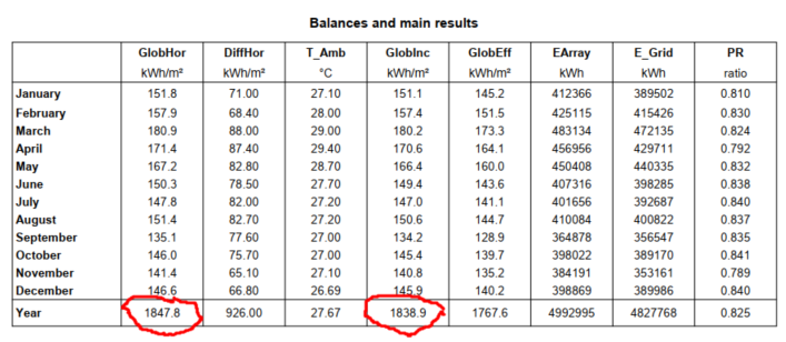
As I understand, the POA value should be greater than the GHI value, but why does it show in our project the result like this?
-
The documentation is not necessarily wrong—it refers to the minimum runtime value of I₀(T) during the simulation, not the user-entered reference value. The difference you see is because PVsyst applies a higher minimum value to I₀\_ref internally to avoid floating-point instability during IV curve calculations.
-
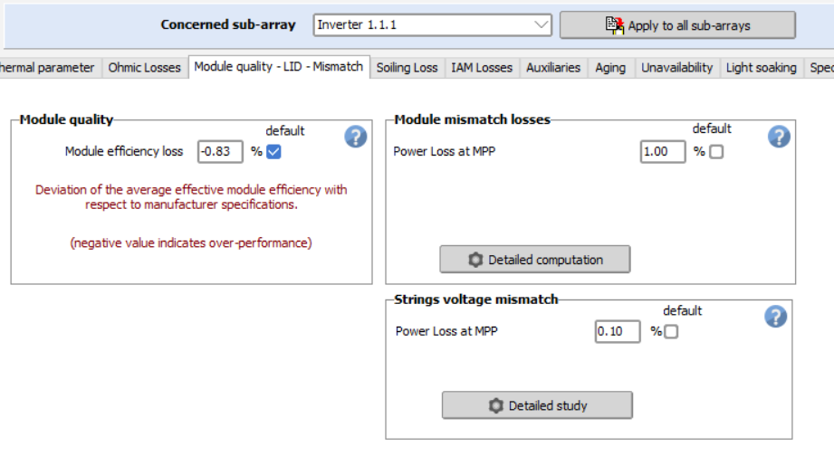
This depends on the PV module you have defined in your subarray. The LID box is only visible when the LID is pertinent, I.e. with crystalline modules: siMono, siPoly, HJT
-
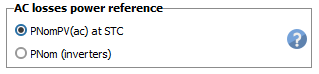
In the AC losses part, the reference power may be either the STC power of the PV array, or the PNomac output of the inveters. This choice is done in the project's settings: In this case the PNomac of the inverters is the nominal power (not the possible max. power at low temperature). NB: In your case the choice of the reference power is the array STC power (nameplate of the PV modules). However the reference power choice affects the ohmic loss parameter when expressed in terms of percentage. The basic definition of the ohmic losses is the cable Resistance. When operating, the ohmic loss is proportional to the square of the current. When expressed as percentage of the power it is proportional to the power. This is explained in detail the help https://www.pvsyst.com/help/project-design/array-and-system-losses/ohmic-losses/index.html. As an example: You have defined a MV lines loss of 1% for a PNom at STC = 8.2 MWp (PV array). Now if you have a PNomac(inv) of, say, 6 MW, the relative loss at PNom(inv) will be 1% * 6MW/8.2MW = 0.73%. You can check that if you change the referenc power in the project's settings, the relative losses will drop accodingly in this dialog.
-
Following the new PVsyst update we must specify the tilt angle we would like to modify parameters for on several different sections of PVsyst. I am concerned that this creates an opportunity for mistakes if each orientation is not modified as needed, and would also like to know why the individual orientation (tilt angle) modifications are necessary. For example, we are to add separate albedo values for each orientation, but how would we have different albedo values based on orientation within a single site? Is there a resource to better understand the new updates to orientation/ tilt so that I can ensure I am using them correctly? Kind regards.
-

PVsyst Aging _ Clarification on Degradation Calculation in PVsyst
André Mermoud replied to Kanagavel K's topic in Simulations
This is explained in detail in the help https://www.pvsyst.com/help/project-design/array-and-system-losses/ageing-pv-modules-degradation/index.html?h=ageing The LID degradation occurs in the first hours of the system operation. It is simply treated as a diminution of the PV module efficiency, whatever the operating year. In your case it should be specified as null. This curve is a warranty for each individual module. It does not describe the average ageing behavior of the PV system. -
Hello, I am performing a simulation and has realised that LID box is not appearing when defining the detailed losses of the system. I attach a picture showing the issue. What is the reason it does not appear and how could I solve it? Thanks in advance. BR, Auxi