All Activity
- Past hour
-
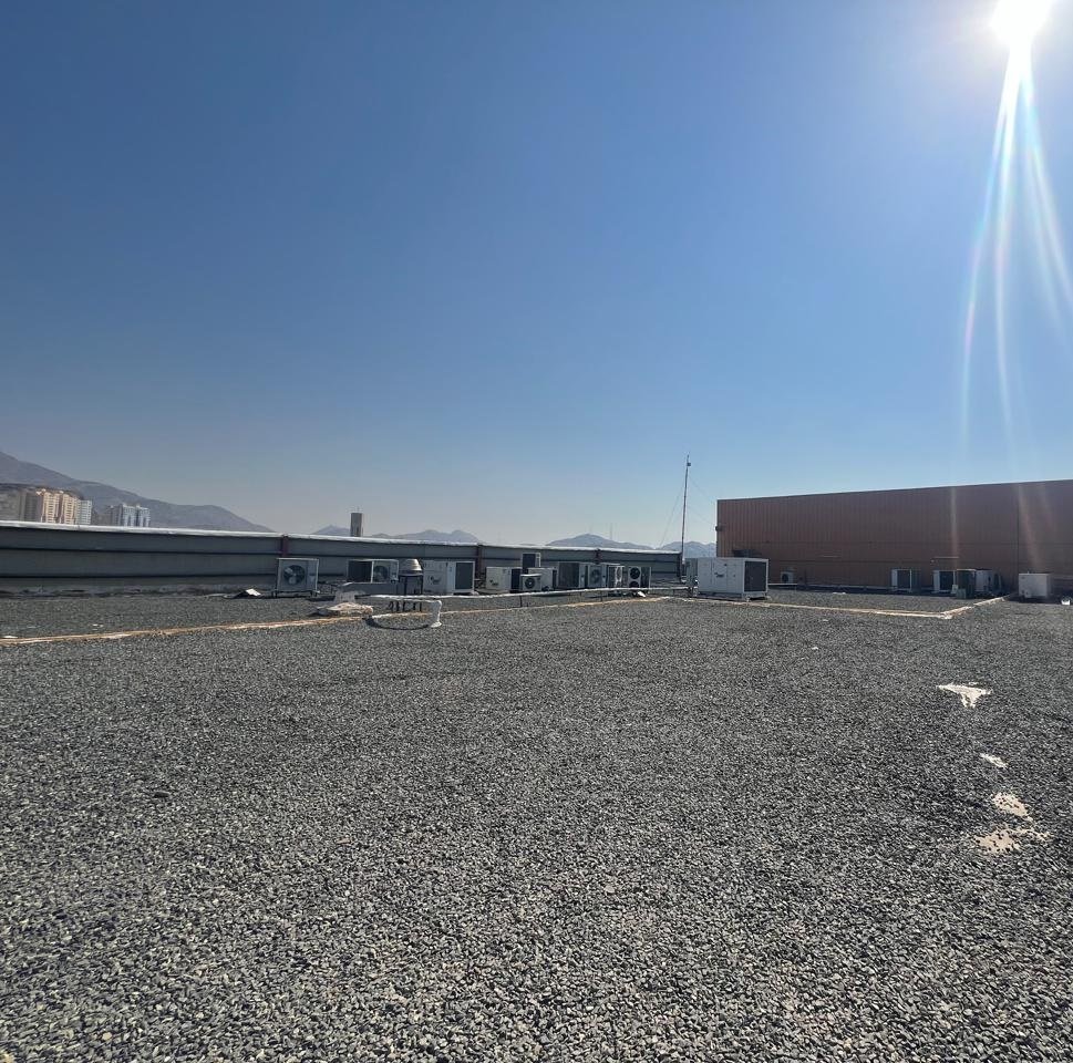
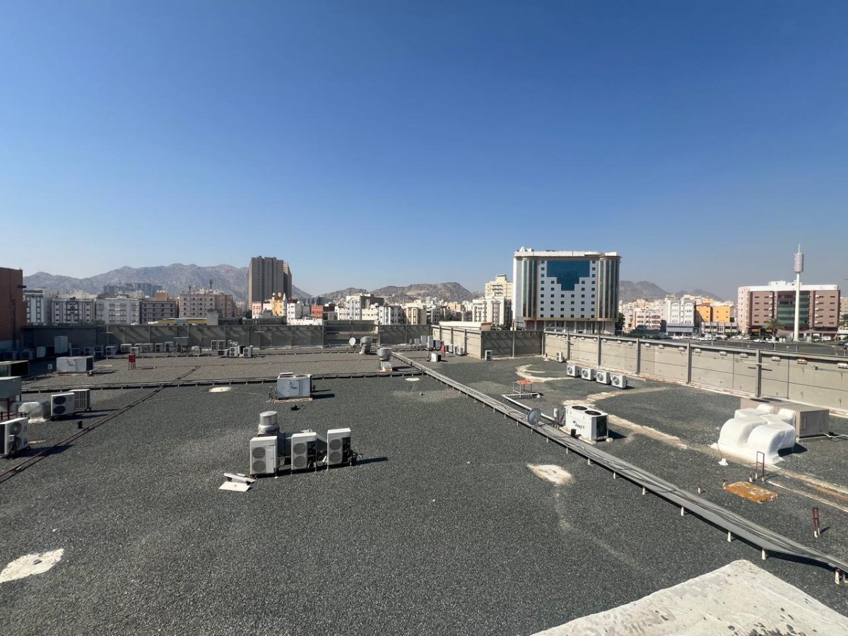
In one of our project sites, the rooftop surface is covered with gravel (dark-colored stone material). Could you please advise on the most suitable Albedo value to use for bifacial module simulation in this scenario? Kindly refer to the attached roof image for reference. Finally, please consider the effect on reflection, as it is a rough surface, not a smooth surface with one color.

- Today
-
 Mohammad Al-Hayek joined the community
 -

Modules following terrain slope in 3D shading scene
Jéremie Bernier replied to emily.denz's topic in How-to
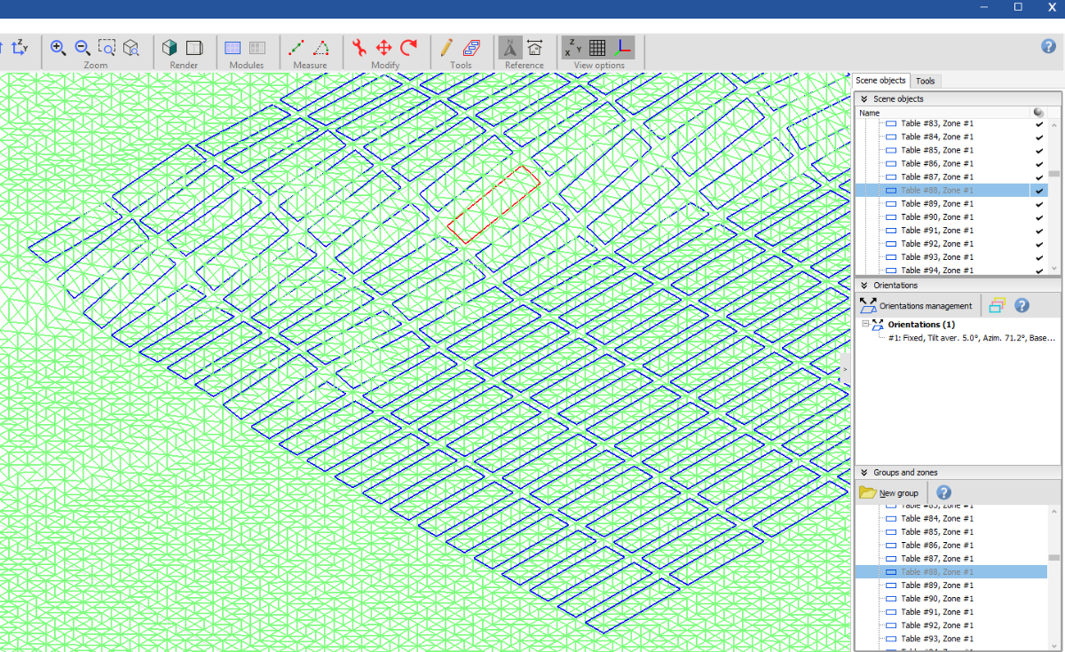
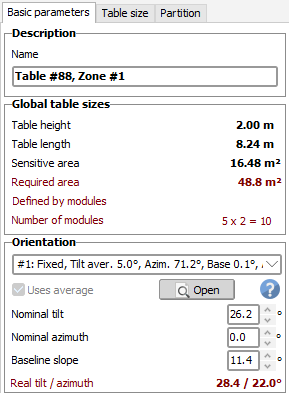
Hello, If you’d like to fill an area on a hill with PV modules, you can use the Zone Editing Tool. Once you've defined the zone using either a rectangular or polygonal area, click on Field Properties and set the desired tilt and azimuth (select Uses average), then click on Fill Zone. Here’s an example of how a filled zone appears on hilly terrain: After filling the zone, you can select and edit an individual table (like the one highlighted in the scene above). You’ll notice that the baseline slope is automatically taken into account. The Basic Parameters of the selected table will also show the actual tilt and azimuth values for that specific table: Hoping this helps you.
-
This is probably due to a bad definition in the PAN file used. I have corrected / securized this problem for the version 8.0.15, to be released mid-august 2025.
-
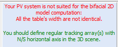
Regularity is defined vaguely by PVsyst. If the system is approximately regular, e.g., patches of trackers or tables that are more or less evenly spaced, then this can be considered “regular” in the PVsyst sense. In that case, you can use the 2D bifacial model jointly with the 3D scene. PVsyst will check the following points: The RMSD of the pitch distribution. If the RMSD is too large, PVsyst will throw an error. You can change the threshold of the error in the advanced parameters. Whether the tables are the same height. If there are differently tall tables, PVsyst will throw an error. Whether orientations have more than 2 rows. If there is only one row of tables, PVsyst will throw an error. The average axis tilt of the trackers in each tracker orientation. If the average axis tilt is too large, PVsyst will throw an error. You can change the threshold of the error in the advanced parameters.
-

Turning on Bifacial when using 2 different module types of different size
Robin Vincent replied to Jig's topic in How-to
The issue lies in the fact the bifacial model is linked to the subarray orientation, but the modules information are from the subarray. I guess from these messages that you may have two subarrays with different modules sharing the same orientation. One easy workaround would be to define two identical orientations, and set one to each of your subarrays. The main drawback of this solution is that your two subarrays won't cast shadows to each other on their rear sides (since the "unlimited" model used for the rear side is only considering mutual shadings). -
Is it impossible to apply the rear system for modeling that is not arranged regularly? I want to apply double-sided efficiency when installing solar power on the ground But solar 3D modeling on the ground can't be represented in a regular arrangement
-
Currently, the rear-side model of irradiance is two-dimensional (cross-section). However, it is compatible with a 3D drawing. If you have a 3D drawing with a regular arrangement of tables, you can activate the 2D bifacial model to compute the rear side irradiance.
-
Hello, In my project, I’m working on the shading construction and I’ve imported a 3D map to simulate a ground-mounted PV system on a hill. I would like the module tables to lie flat on the ground, following the slope of the hill. However, when I set the tilt angle to 0°, the modules are placed vertically. My intention is for the modules to be flush with the terrain surface—meaning their tilt should automatically adapt to the slope of the ground at each point. How can I configure the system so that the modules follow the terrain slope correctly? Thanks in advance!
-
Hello In the case of using two-sided modules these days, there is an issue about calculating the efficiency of the back and adding it to the module capacity. As far as I know, the efficiency of the double-sided module is applied only to the 2d model, but is there any way to simulate the power generation time by applying the double-sided efficiency in the 3d model?
- Yesterday
-
 I have a few sites where I get an error message stating: This will NOT simulate unless I select "Don't use in the simulation" under the Bifacial Model. Is there anyway around this? Thanks!
-
-99 is an invalid value for all parameters. The extrapolation feature has been removed and any missing value will be treated as missing (0 irradiance). The help will be corrected in the next release. I apologies for the confusion.
-
 Dipali joined the community
 -
Thank you for your response. Can you please clarify what parameters the -99 does work for?
- Last week
-
 PVsyst Jan joined the community
 -
 Karan Kumar joined the community
 -
 Bumping.
 -
Bumping this again.
-
I have the same question as LauraH.
-
 Omar joined the community
 -
One of my supreme annoyances over 11 years. PVsyst did final add ac losses and MPT losses in that big update so they did add KVA or base rating for other ac losses like power industry does. So we can enter load losses for equipment at certain ratings on right side. But for some reason the PVsyst just couldn't fix ac cable losses. I think it still still still rides with the MWdc installed on variants. PVsyst opted to keep tying it to DC rating * efficiency or something I can never decipher. PnomPVac at STC which makes no sense since AC power is independent of "standard test conditions" which is related to modules flash test nameplate and dc power...It's all tied back to a time I bet with dc/ac ratios were 1 to 1 so it all got mixed up. And Pnom (inverters) is an arbitrary .ond file rating, not what MVT are load loss tested too. All very fun to navigate. I sympathize.
-
 vlite joined the community
 -
Unfortunately, it is impossible to extrapolate irradiance, missing data or invalid data (-99) will be set to 0. This is due to the intrinsic variability of the irradiance. I will clarify our help page on this point.
-

PVSYST cannot open any project, old or new.
Laurent C replied to FrancescaTucci's topic in Problems / Bugs
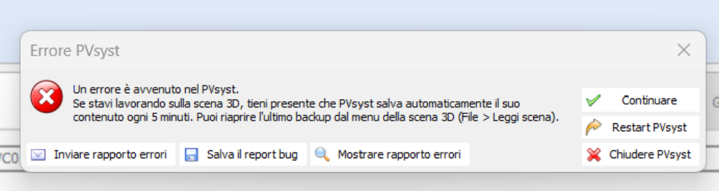
Hello Francesca. Next time you encounter this issue do not hesitate to use the button to send us the report directly. Also, you can still email us your logs (File > export logs) and send them to support@pvsyst.com. Regards, Laurent -
 Whilim Son joined the community
 -
 Sunpower zone joined the community
 -
Hello, I created a project yesterday but opening the 3D Scene from Layout modules, PVSyst gave me an error. After that, every time I try to open an old or even a new project, it shows me this error. the result is that I cannot do anything on PVSyst, nor load, open or create a new project.
-
 FrancescaTucci joined the community
 -
Automatic mode will select the tracker with the highest GCR as reference. It is an alternative way to select the tracker pair. If you deselect the tracker pair, the parameters shown in Pitch, collector width, etc. can be manually adjusted.
-

Modeling modules with different powers in a single MPPT
Luca Antognini replied to Gustavo Pianovski's topic in How-to
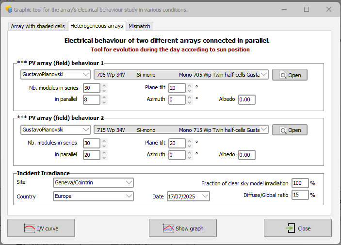
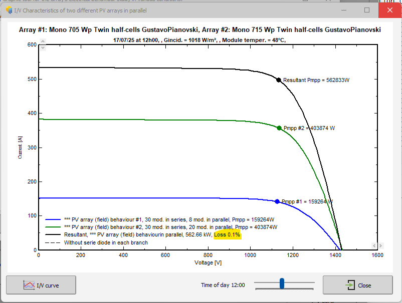
Hi! If you could provide the full detailed about the module (the missing Isc and voc values) that would be easier to reproduce your example. The simulation you want to describe consists of different strings connected in parallel into a single MPPT, which will create some small losses of voltage mismatch between the strings (they don't have all the same Vmpp). In this view, none of the two first simulations setup you describe can include this effet, as they both represent strings connected either to different MPPT or different inverters. They won't suffer from voltage mismatch and lead the same results as you pointed out. And there are no ways to define exactly the configuration you are describing from the system window (as this is quite an unusual one). The correct approach is indeed to add these losses later in the detailed losses menu, by evaluating them roughly (they are rather small in the end) independantly of the main simulation. Now, for the difference between your calculation and PVsyst calculation, I see first that in your table you update the voltages to lower values but keep the current unchanged. However, if you reduce the voltage from MPP, it will increase the current and therefore the power is slightly higher than in your evaluation. And consequently the losses would be smaller. It is really not surprising that PVsyst gives you such a small value when you have such as small difference of voltage among strings. Another impact you should consider is that the MPP of your configuration will be closer to the one of the strings formed of 710W and 715W pannels than the one of the string composed of the 705W, because they have much more strings in parallel (36 and 37 vs 8). Therefore there is more to loose to move the voltage for those one than for the 8 strings of 705W pannels. If you want to see this effect, you can also check it with another tool : Tools / Electrical behaviour of PV Arrays / heterogeneous arrays (note: the limit of the tool is 20 strings but it is not a problem for us). You can see that the relative losses are smaller than 0.1%. And this is already a pessimistic scenario here. So In the case of your system you could consider neglecting completly those voltage mismatch losses.
-
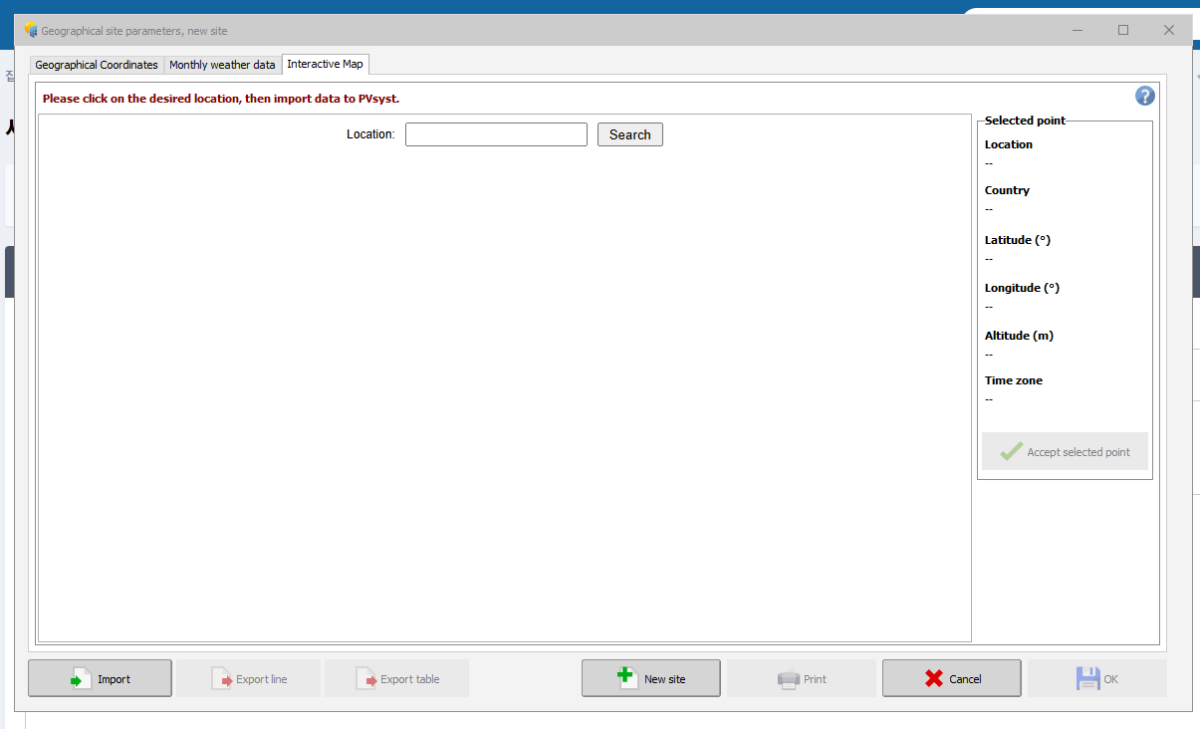
Unable to look up geographic location
Laurent C replied to YoungWook Hwang's topic in Problems / Bugs
Hello, Thanks for your message. Please udpate to the latest 8.0.14 version, it contains both Bing and Azure as map provided, I suggest you use Bing as it is available workdwide. regards, Laurent -
This is a bug, I have created a ticket to address it. In past versions, it used to be present in the report.
-

Simulating multiple orientations in a single subarray
Michele Oliosi replied to Jason Brandt's topic in Shadings and tracking
Sorry, this warning is not appropriate in your setting, we still need to address the way it is triggered so that it becomes more relevant. I think it was added with the case of different nominal orientations in mind. But currently, for your case, i.e., one nominal orientation with many variations due to the topography, the way to go is: use only one orientation. This has one drawback: the averaging error and the mismatch caused by the individual orientations are not taken into account, i.e., on this end the calculation is a bit optimistic. But since our calculation is already conservative in other ways (e.g., backtracking modeling), I do not think this small underestimation of losses is critical. In the future, we want to account for these two losses we are yet missing. -
Hello. There is an error with pvsyst 8.0 version I'm inquiring about this. From 8.0 version, the new map coordinates are not searched. I've upgraded, deleted the file and reinstalled it, but it's the same. The 7.0 version will be viewed. I would like to ask you to check if there is any problem with the 8.0 version. Thank you.