Search the Community
Showing results for tags 'inverter'.
Found 3 results
-
We are performing a simulation with an inverter brand XXX at a site in Spain. During the analysis, we observed differences between the simulation data and the DC current values defined in the OND file. - In the Main Parameters window the inverter has a rated AC power of 4504 kW, with a maximum DC current of 5002.6 A, for a voltage U_DC of 915V. According to the manufacturer's data sheet these values correspond to operating conditions at 40 °C. (See Figure 1) Figure 1 - In the Energy Managment tab, the "external ambient temperature (outdoor installation)" option is selected. See Figure 2. Figure 2 - In the simulation, the site shows maximum ambient temperatures of 43 °C, without reaching 50 °C. - However, when plotting the simulated DC input current and voltage points (extracted from the Uarray , IArray variables), it is observed that the maximum current values never exceed values expected for temperatures below 50 °C curve profile, not even close to the 40 °C profile (which would be the expected behavior). Next figure (Figure 3) shows inverter input curves (V,I) for different temperatures and in yellow (Uarray, Iarray) points from simulation. Figure 3 🔧 Additional details: - Tests have also been performed by manually modifying the temperature derating profiles, even at extreme conditions, but the DC current results in the simulation do not change. May be PVsyst is using the 50 °C inverter curve by default to limit the inrush current, regardless of the actual site temperature. Below we copy part of the OND file where the inverter operating limits are defined. Converter=TConverter PNomConv=4504.000 PMaxOUT=4504.000 VOutConv=660.0 VMppMin=915 VMPPMax=1300 Vmpp_PMax=915.0 VAbsMax=1500 PSeuil=20005.00 EfficMax=97.00 EfficEuro=95.00 FResNorm=3.00 ModeOper=MPPT CompPMax=Lim CompVMax=Lim MonoTri=Tri ModeAffEnum=Efficf_PIn UnitAffEnum=kW IDCMax=0.000 INomAC=3500.000 IMaxAC=3940.000 TPNom=40.0 TPMax=25.0 TPLim1=55.0 TPLimAbs=60.0 PLim1=4001.000 PLimAbs=2001.000 PInEffMax =1800.000 PThreshEff=49.90 HasdefaultPThresh=False ❓Question: - Is there any reason why PVsyst limits the input DC current according to the 50 °C profile even when the maximum ambient temperature conditions of 43 °C? - Is it possible that PVsyst is using an estimated inverter internal temperature different from the ambient temperature to apply the curves? - Why the simulation results do not show values with data at 40 degrees of the inverter? Attached is also the comparative graph between the inverter input curves (by temperature) and the simulated values. We thank you in advance for your attention and any clarification you can provide, we remain attentive for any additional information you may require.

-
after update pvsyst version 8.0.4 Why does the problem still occur?
-
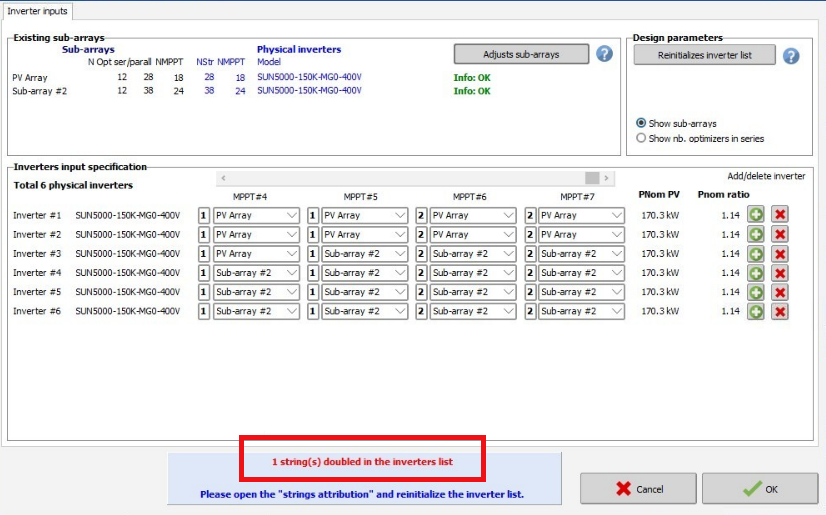
Hi Everyone, I am experiencing a configuration issue while simulating a system with multiple inverters and MPPT inputs in PVsyst. Here are the details: - System Configuration: Inverter 1: 5 strings of 20 panels in series and 5 strings of 18 panels in series, totaling 10 strings. The inverter has 12 MPPT inputs. Inverter 2: 4 strings of 20 panels in series and 4 strings of 19 panels in series, totaling 8 strings. The inverter also has 12 MPPT inputs. - Issue: The error message states: "The sum of the MPPT inputs in the sub-arrays is not a multiple of the number of inverter MPPT inputs." PVsyst interprets the configuration as using 1.5 inverters instead of two separate inverters if I did not used MPPT Sharing. Could you please provide guidance on how to configure PVsyst to accurately reflect the use of two inverters, each with their respective string configurations and MPPT inputs? Thank you for your assistance.