rcalvo
-
Posts
7 -
Joined
-
Last visited
-
Hi, From the last version 6,68 I found always blocked the option for the temperature for nominal power evaluation. I can´t change the options, is blocked as the last time I saved the file in the previous version. http://i64.tinypic.com/307uw5z.png Is it a bug? Thanks.
-
I don´t undestand what are you tryind to do Why don´t put only the PV plane at the inclination of the "tilted objet"? If the objet is below the PV plane... In other case, to set or move objets,PV planes...etc, is very important to know where is the reference point of the object
-
Hi, The PV field detailed system losses parameter in the auxiliary energy losses I have some doubts: based on the following data from manufacturer .OND file 1: Inverter Losses: This is provided by the manufacturer, in the .OND file. "Continuos auxiliary loss (fans, etc)" Are this the self-consumption losses in operation of the inverter? "...from threshold on oper. power" in the .OND file it´s called "...from output power". I don´t understand this kind of losses, would you mind to explain in more detail? 2:plant losses: "Proportional to plan operation power(W/kW)" Are this losses in W per kW peak or nominal? They are the same and continuos losses all hours of the day/year? "...from threshold o oper.power" Are this losses into account only the hours from threshold on oper. power(operation of inverter)? 3: Nigth Losses: What kind of losses are this? Why excluding the inverter nigth loss? if the manufacturer set nigth losses (400 W in this case), where I use it? Thanks.

-
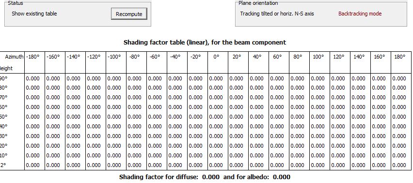
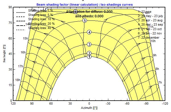
Hi I have a doubt, wen I run a simulation with horizontal tracking system (with backtracking), the shading factor in tables and Iso-Shading diagram are "0" (in al components, beam, diffuse and albedo), but in the final system loss diagram I have a "Near Shading: Irradiance Losses" around 1-2%. Why this happens if in the shading factor table all the results are "0"??? Results of the Near Shading calculations: Results of the final simulation losses Thanks
-
You usually size your installation based on the STC peak power, the power tolerance is a range of power(statistical), maybe all your modules will be in the 0% or all in the 5%...you will never know before the making the engineering, so size the installation based on the statistical maximun power tolerance, will be more expensive. The inverter can operate over the "maximun power input", symply limit the input (modify MPPT) and output power. "Direct" does not neccesarily mean "perpendicular". The STC test is with a Artificial ligth, thats include the Direct and Diffuse component
-
Thanks for reply But in all pv panels data sheets a term called power tolerance usually is (-0/+5), this term means panel output can exceed peak power by 5 watts or what? :?: There is a manufacture tolerance. The peak value in the datasheet it´s the "average" of the electrical parameters of the same PV modules model. In facts, each manufactured module have different electrical characteristic (slight difference). The "power tolerance" in manufactorer datasheet menas that your PV module, for characteristic of the manufacturing process, can exceed the peak power in +5%. For example, you have 3 modules of 300Wp with -0/+5 (identical brand and model) , according to manufacturer, you can have: - 1 module 300Wp (+0% power tolerance) - 1 module 303Wp (+1% power tolerance) - 1 module 315Wp (+5% power tolerance) .....
-
Hi, In the FAQ, on topic "How to adjust the NOCT value ?", for the decision of "eliminate" the NOCT approach, you refer a NREL study about the temperature behavior of many modules with differents NOCT values. Can you quote this study or the full title to search it? I would like to read it because it must be very interesting. Thanks.