Aparna
-
Posts
14 -
Joined
-
Last visited
Everything posted by Aparna
-
Hi, I am using PVsyst v.6.72 to estimate the generation of a bifacial tracker. However, I was not able to create the following conditions in bifacial systems with PVsyst : a. with vertical axis trackers, dual axis trackers or tilted axis E-W trackers etc. b. with shading scenes for any array type c. with specular reflectors d. with varying albedo patterns on the ground e. to define exact shading pattern on back side of PV module due to support structure or array shading pattern on the ground due to the array. Is there any option to incorporate a shading scene with a bifacial system in PVsyst v.6.72? Could you please tell me the above simulation option for the above systems and the option for the user to use ray-tracing & shading scene definition to more accurately predict the energy generation from bifacial arrays are incorporated in any of the more recent or upcoming versions of the Software? Thanks and regards, Aparna
-
Hello, I am comparing the hourly simulation outcome of a backtracking HSAT (+45, -45) at different hours for a day with the hourly simulation results of different fixed tilt arrays with equivalent tilt, orientation and system configuration for the corresponding hours of the year. System details: 3600 REC 320Wp modules - total 1152kWp; 1 ABB 1000kW inverter; 4m pitch; 30 x 1.97m wide 118m long arrays. All loss factors are kept equal for HSAT and FT arrays. It is seen that the backtracking HSAT has zero shading (electrical) losses for all hours of the day, whereas the corresponding fixed tilt systems are subjected to shading losses. For instance, I am referring to the hourly simulation result for the two systems for 7:00 am March 31 : Backtracking HSAT is at a tilt of the 15degrees, -90 azimuth and inverter output power is 256569W with zero electrical shading loss. The corresponding fixed tilt array with 15 degree tilt and -90 azimuth gives an inverter output of 177123W with 67672W of power lost due to electrical shading effect. Despite the similarities in the system details, why does the fixed tilt system suffer shading losses, whereas the HSAT with a backtracking tilt angle of 15 degree and -90 azimuth is not subjected to any electrical shading loss at the same hour in the same day? Hope someone can help me understand the reason for the disparity in these simulation results. Regards, Aparna
-
Dear Mr. Mermoud, There is no inconsistency in the query. What you see in the shading scene is also a tracker. Each module is mounted on individual single axis trackers (2m x 1m) with an axis tilt of 3degrees. This is why the shading scene snapshot has the appearance of a fixed tilt system. Hope I have clarified. Regards, Aparna
-
The system definition and the shading scenes used are the same in both cases, which is why this question arose. In fact the new variant for "module layout" calculations were created from the variant where shading definition is "according to strings". The module orientation is also the same in both cases - which is in landscape mode. Please find attached is a snapshot of the shading scene.

-
Hi, In my simulation of a tilted axis tracker system with NS axis using PVsyst V6.38 acc. to the following two variants, a. with near shadings definition according to strings b. with near shadings definition in detail according to module layout. shading loss results were observed as below: a. Near shadings definition according to strings : irradiance loss (3%) electrical loss acc. to strings (0.9%) b. Near shadings definition according to module layout : irradiance loss (2.9%) electrical loss detailed module calculations (0%) Please clarify why the irradiance and electrical shading loss is higher in simulation as per string definition and decreases for a more detailed module level. How is the effect of shadows from portrait and landscape sides evaluated in either cases? Looking forward to your response. Thanks and regards, Aparna
-
Hello, I am working on a project to find the impact of different ARC on solar PV cells and glass. How can I use PVsyst to simulate the performance of different ARC materials? In this respect I would also like to know: Does the b0 value in the IAM factor tab (in detailed losses) consider the impact of ARC on glass and cell as a single factor? Is the value of b0 = 0.05 representative of SiNx ARC on cell? How do I modify the b0 values to capture the use of a new ARC material other than SiNx? Thanks and regards, Aparna
-
How is angle between planes calculated for heterogeneous tilt system? What is the relevance of the predefined 25° limit?
-
Hi, I tried simulating an E-W facing system in PVsyst 6.32. The simulations run were: 1) by conecting the E and W facing strings to the same inverter and 2) by connecting E and W facing strings to different inverters. The output energy was same for both simulations. The mixed orientation mismatch loss for case 1 was only 0.1% and zero for case 2. The near shadings loss for case 1 was 0.3% and for case 2 it was 0.4%. All other losses remain the same. How can the irradiance level loss vary when the layout remains the same? What is the princpile behind the calculation of "mixed orientation mismatch loss"? The value of 0.1% for this loss appears to be too low. Please clarify. Thanks and regards, Aparna
-
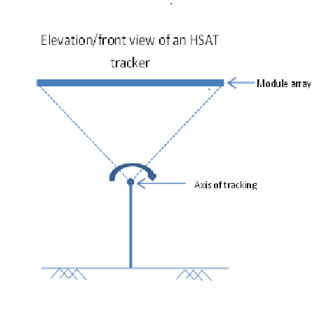
Can the axis of tracking of a tracker be shifted to a separate plane i.e., can the module array and the tracking axis lie on two different planes so that the module array would appear to orbit around the axis? An image showing the idea is attached.
-
Hi Unilhexio, Yes, the systems use modules and inverter of the same model and manufacturer. Both systems have been designed and installed devoid of any shadings. Could you please explain how the wind exposure can affect the module performance? Thanks, Aparna
-
Hello everyone, This query is based on an observation on a rooftop plant installed at our office. We have a section that is comprised of E-W facing sheds at an inclination of 10 degrees and a section which has S facing sheds at an inclination of 10 degrees. It has been observed that the inverter connected to the E-W facing sheds give a higher energy output than the inverter connected to the S facing sheds, throughout the year and also, this difference in energy generation is highest in the summer months and reduces in the winter months. We have also measured the GHI for the location using a pyranometer. The tilt radiations were then generated in PVsyst. It is seen that the radiation on the tilted plane of the south facing sheds is higher than that on the E-W facing sheds. We are trying to analyse the possible explanations behind this observation. Has anyone else come across a similar situation ? Could anyone offer a reasoning ? Thank you.
-
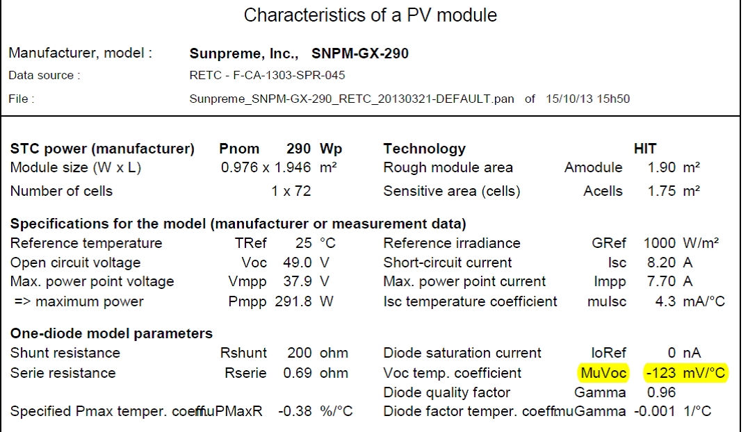
Thank you for you response. The issue I am facing is that the PVsyst screen display and the pdf of the same PAN file are showing two different values of temperature coefficient of voltage. I will attach my screenshots here. Could you please tell me why this is happening?
-
Hi I encountered this issue while examining a PAN file provided by a manufacturer. The PAN file was imported into PVsyst version 5.68. The PVsyst screen for PV module definition shows the value for muVoc as -153mV/C whereas the print out of the PAN file from PVsyst shows the value of muVoc as -123mV/C. An explanation for this discrepancy would be very helpful. Has anyone else encountered such a problem? Thanks, Aparna
-
Hi, I am a new user of PVsyst software. I would like to know how one can find the P90 value for a particular P50 simulation result in PVsyst 5.68. Is this provision available in this version of PVsyst? Does PVsyst help documentation describe how to manually calculate the same? Thanks and regards, Aparna