

Aidenn
-
Posts
32 -
Joined
-
Last visited
Posts posted by Aidenn
-
-
Hi Linda,
Thanks for the reply!
May I ask if its always the case for MPPT sharing, to use Auto-equal. Pnom option?
Thanks,
Aidenn
-
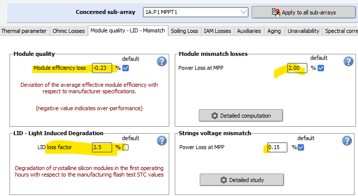
Hi PVSyst Team,
Can we determine these parameters with the module info alone? I'm using Jinko Solar - JKM590N-72HL4-BDV and JKM595N-72HL4-BDV/
Please show how do we come up with the values.

Appreciate your help,
~Aidenn
-
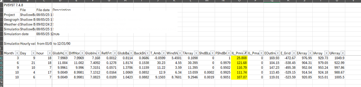
Hi PVSyst team,
Can someone explain how do PVSyst determine the clipping loss on these periods? I attached also the setting for the MPPT sharing applied for the system. Please let me know for any other files needed to identify these losses below. Thank you!
-
Hi Linda,
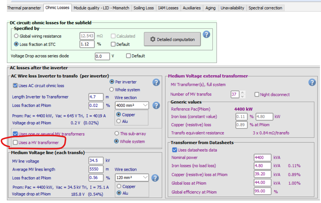
There's already a PVSyst file with all inputs are present. The request is to generate another report to have HV losses excluded. Is unticking this box the correct way to exclude the HV losses? (see image below)
-
Hi,
PVSyst report with HV transformer and HV transmission line losses excluded. How to do this?
-
You're a great help Jéremie! Thank you.
-
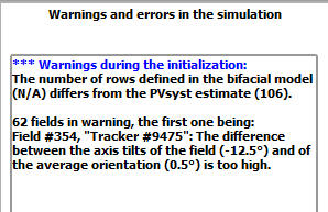
Hi PVSyst Team,
I already generated the PVSyst report and these warnings appear during initialization.
The 3D scene comes from PVCase and a TFT. Can someone assist how to deal with these errors? Appreciate your help.
-
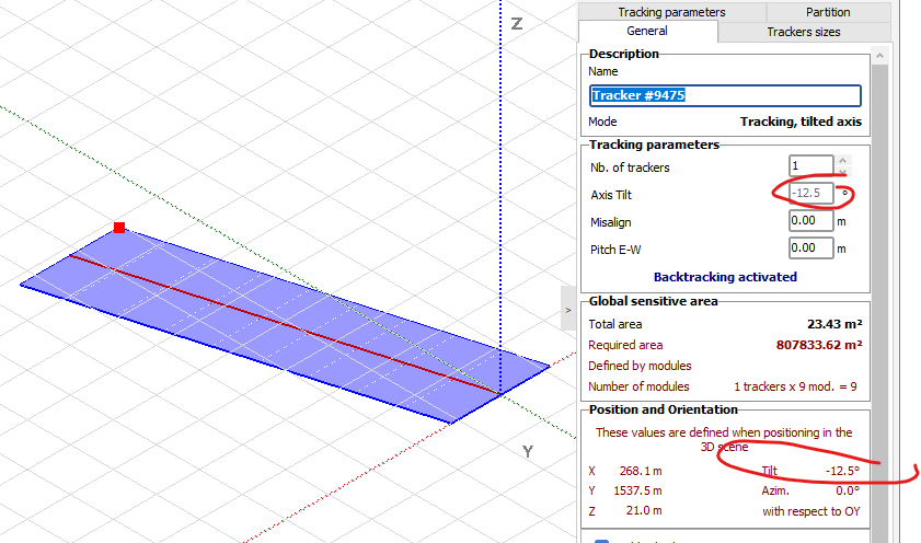
Do I need to change my settings so that the PVCase imported scene should show the trackers altitude correctly?
-
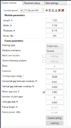
Hi PVSyst Team,
I'm designing TFT exported from PVCase to PVsyst.
1. The trackers imported have no bays. Is this because the modules are connected on the same string? The longer tables are 4string of 28 modules and the shorter ones are 3 strings of 28 modules.
2. If this is correct, the treatment is same as non-TFT approach using according to module string and Module layout result for the electrical approach?
3. Partition guidelines?
Thank you,
Aidenn
-
Hi PVSyst Team,
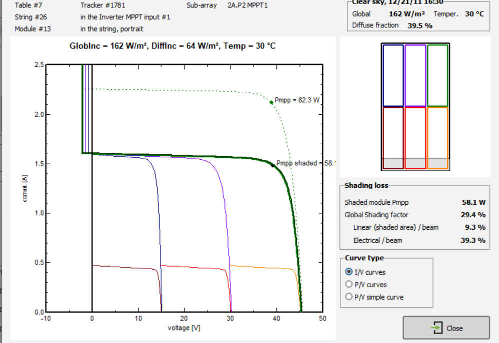
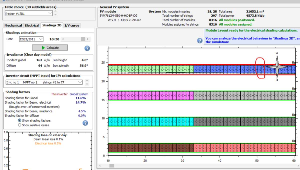
Since my scene is too large, I created a smaller scene exactly for 1 central inverter. Base from the module layout I have this values.
QUESTIONS:
1. Following the guide from PVSyst Help screenshot above then = 29.4% - 9.3% = 20.1% (Is this the fraction for electrical effect that I will be using in the Nearshading ?)
2. I also did a 100% Fraction for electrical effect but I'm not sure about the definition of "regular (row-to-row)". can you further explain this? By the way my scene have only tracker tables without trees or other shading. The terrain comes from PVCase. and this is the result.

-
Hi Jeremie,
What is the resolution for this? I'm having the same issue.
-
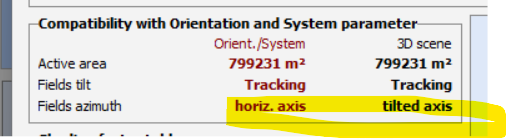
Hi PVSyst Team,
I would like to know how to change the PVCase Fields azimuth from tilted axis to horizontal axis. Or is this predetermined by PVCase? The tracking model to be used in my project is the ATI DuraTrack HZ v3 (see specs below)
-
Hi Michele,
Follow up question. with a different scenario. What if I have a LANDSCAPE orientation 84 modules 3 string AT 28 module/string. What will be my partition for my x and y?
-
Hi PVSyst Team,
It's my first time using PVCase file for the Nearshading scene and some trackers are below the terrain mesh. Can I do auto altitude or should the adjusment be done on the PVCase software?
-
Thanks André
-
Hi Jeremie. I've received your response. I've followed the csv format as per PVSyst guidelines but same thing happened. Please advise
-
Hi Admins,
Is Bifacial Trackers possible for uneven terrain?
-
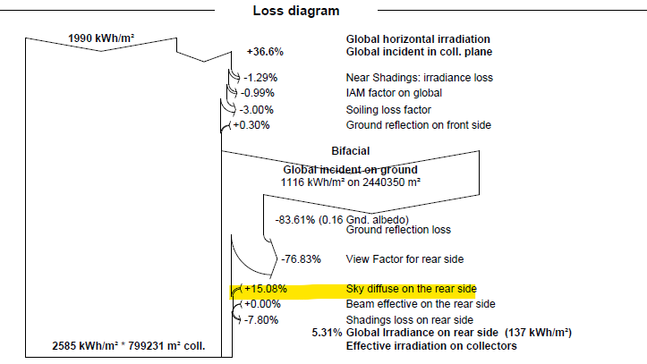
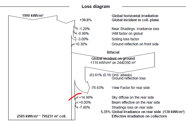
Hi PVSyst Team,
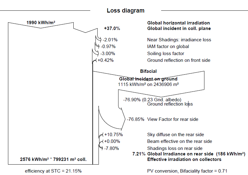
I simulated an option for Linear Shading and According to Module string. In the reports, the only difference in the loss diagram is the Sky Diffuse on the Rear Side. Can you explain why this happen?
The highlighted one is the " According to module string"
Thank you very much.
-
I've sent the CSV. Hope to hear from your team soon. Thank you.
-
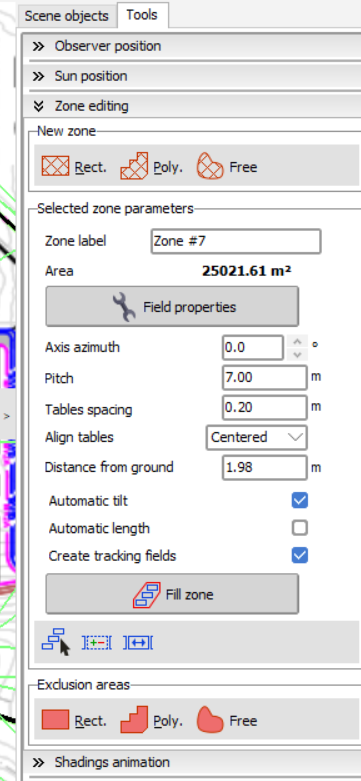
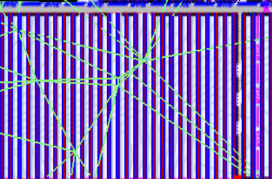
Hi PVSyst,
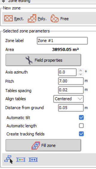
I'm designing a 3D near shading where the tracker N-S is on an uneven ground. I got csv file from Google Earth. .kml.
I used zone > create tracking fields > automatic tilt > set automatic altitude too.Still elevations are visible above the installed tracker. Do you have any solution that. Thank you.
-
Yup that solved it. Thanks Michelle.
Another inquiry in the same project.
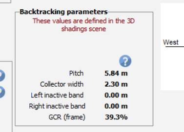
Is it due to the csv file downloaded that I have varying pitch? This one is from the orientation tab saying my pitch is at 5.84m. (see image on the left) then my field properties on the near shading is 7.0m. The correct one is at 7m and 32.8% GCR.
-
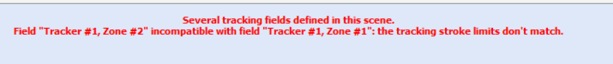
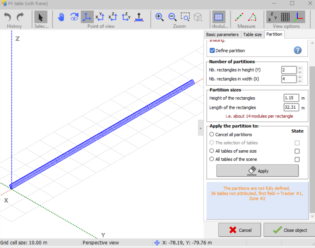
I'm experiencing this errors. I'm using Zone > Create tracking fields in the nearshading using a csv file.
This rectangle has 4 strings and a half cut module. Kindly advise
-
Got it!
I already replied to our email thread "How to do partitioning and Fraction for Electrical Effect," not reading your comment here in the forum.
Thanks for the help Muhammed.
-
Hope someone can enlighten me here. Thank you!
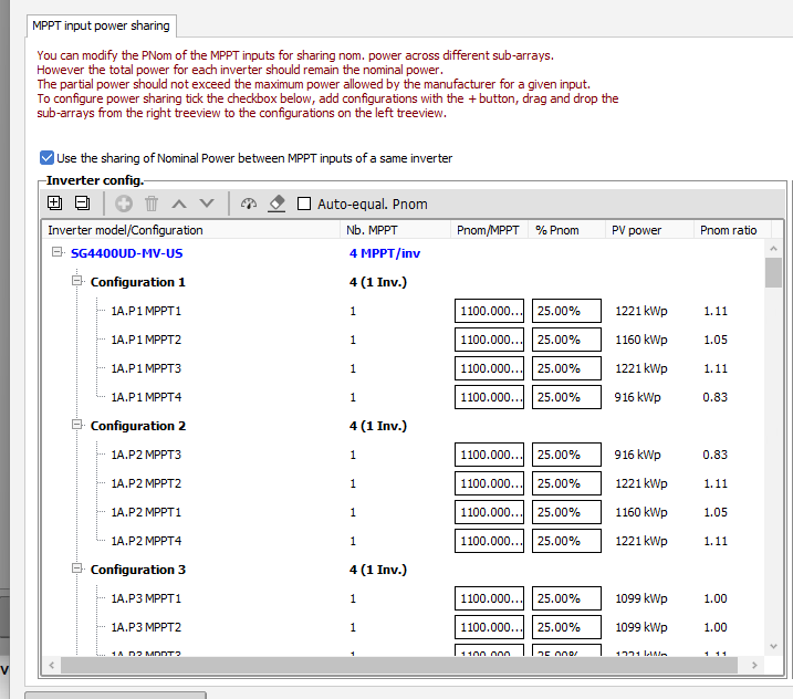


POWERSHARING - # of MPPT of the sub-array exceeds the MPPT capacity of inverter
in Simulations
Posted
Hi PVSyst Community,
Is there a turnaround so I can define this config in the powersharing option in PVSyst?
For context, 1A.PCS.7 uses SG4400 as inverter and at 27m/s. It exceeds the 4MPPT capacity of the inverter and the PVSyst reads this configuration as 2 INV instead of 1.
MPPT1 - 585W - 81str
MPPT2 - 585W - 82str
MPPT3 - 585W - 47str
590W - 36 str
MPPT4 - 590W - 20 str
595W - 60 str
Thanks for the help!