Irakli Bezhuashvili
-
Posts
17 -
Joined
-
Last visited
Everything posted by Irakli Bezhuashvili
-
Dear PVsyst Team, I would appreciate your clarification regarding the definition and use of the Albedo parameter in PVsyst. In the software, the Albedo value appears in two different locations: Project Settings → Site → Albedo System → Bifacial System → Albedo Could you please clarify: What is the functional difference between these two Albedo inputs? In bifacial simulations, should both values always be identical for consistency? kind regards, Irakli
-
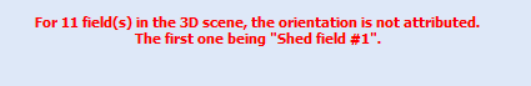
I have the bellow message in PVsyt. Can you please tell me how to attribute orientations in 3D scene? Quantity of PV modules correspond each other in "System" and "3D scene".

-
Yes. thank you
-
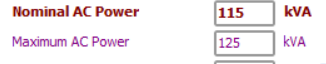
I am using the SUN2000-115KTL-M2 inverter, which has the following specifications: Maximum AC Power: 125 kVA (at cosφ = 1) Nominal AC Power: 115 kVA I plan to configure the inverter to operate at its maximum AC power of 125 kVA. However, I noticed that PVsyst uses the nominal power (115 kVA) for its calculations. Could you please advise how I can reflect the maximum power configuration (125 kVA) in PVsyst to ensure accurate generation calculations?
-
I am using inverter "SUN2000-115KTL-M2" which has maximum AC power 125 kva at cosf 1 and 115 kva nominal power. I am going to configure the inverter on maximum power 125 kva. How should I reflect this in PVsyst, because PVsyst calculates generation on 125 kva? Thanks in advance
-
Hello, I want to generate report which will show electricity monthly generation for several years (10 years) for different probabilities, for example P50 and P90. Can you please helm how to generate such report?
-
Inverter maximum input voltage mismatch with array Voc
Irakli Bezhuashvili replied to Irakli Bezhuashvili's topic in How-to
Thank you for the help -
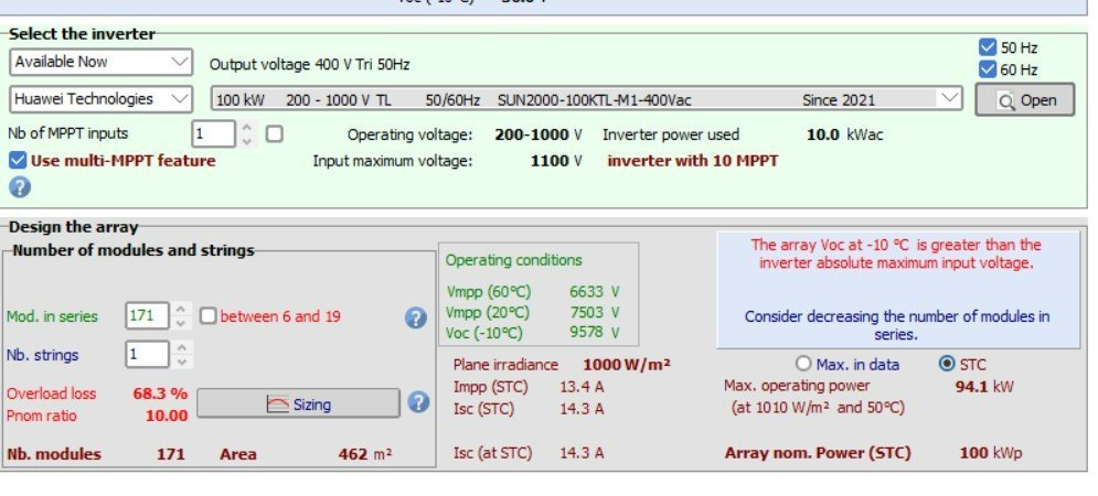
Hello, In the "Setting" dialogue, I have the following notification: "the array Voc at -10° is greater than....." (please the the attached screen 1). I reduced "Lower temperature for absolute voltage limit" in the ""Project setting" dialogue, but the problem hah not been solved. I also tried to reduce number of modules, but I had to reduce several times the modules quantity the problem to be solve which is not correct, because capacity of plant is 150 kW and both inverter total capacity is also 150 kW. Can you please tell what kind of mistake I make? Attached is inverter and module technical specifications (See screen 2, 3 and 4).
-
Different azimuth in Near Shadings and Orientation tabs
Irakli Bezhuashvili replied to brunok's topic in How-to
Yes I works with topography. The PVsyst aligned solar tables to the field surface based on the topo map, but in reality we will have all the tables with tilt 30 and azimuth 0 (we plan to design the support structures in this way). changed/aligned azimuth and tilt reduces electricity generation. -
Different azimuth in Near Shadings and Orientation tabs
Irakli Bezhuashvili replied to brunok's topic in How-to
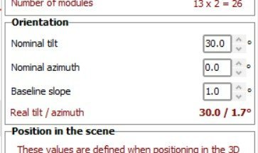
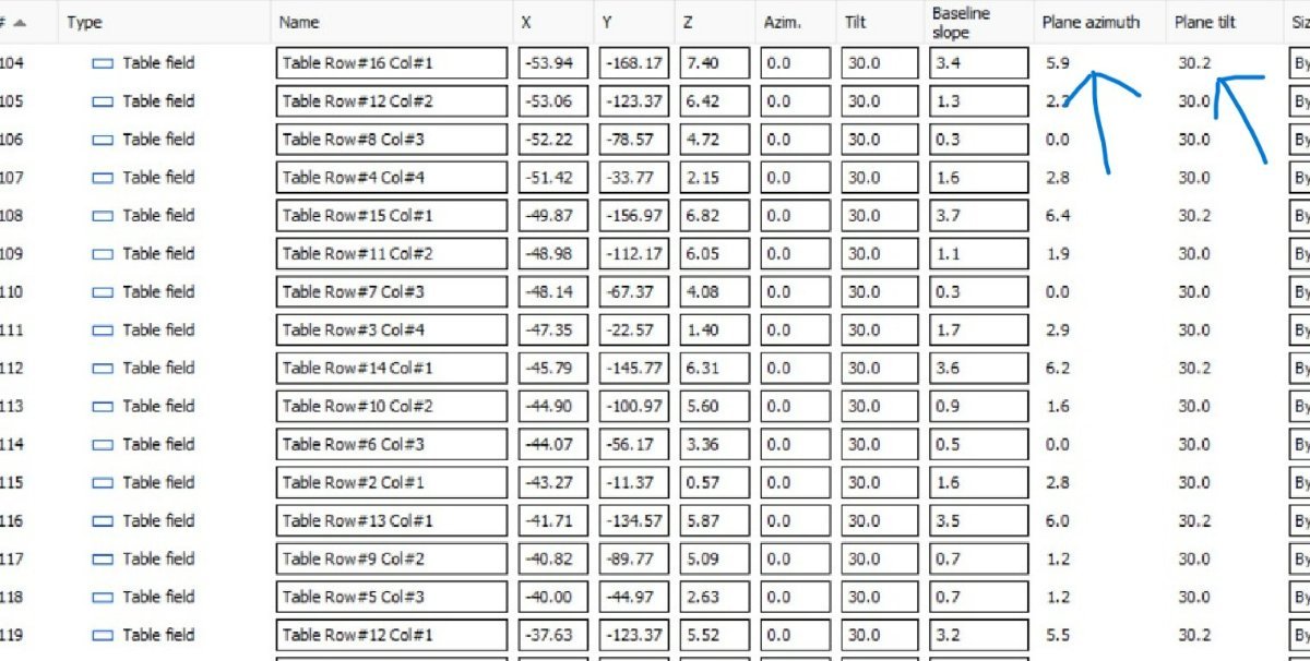
Thank you for prompt reply. The box which I want to change is not editable, I click but is has no affect. Please see the attached file "Screenshot_1" where I indicated with arrow the field which I want to modify (Nominal-real tilt and azimuth). Nominal tilt and nominal azimuth has modification function, but I want the nominal tilt and nominal azimuth to be equal to real tilt and azimuth, That is why I want to change real tilt and azimuth. For example table filed #104 has plane azimuth 5.9 which has to be 0 and plane tilt is 30.2 which has to be 30.0. Thank you
-
Different azimuth in Near Shadings and Orientation tabs
Irakli Bezhuashvili replied to brunok's topic in How-to
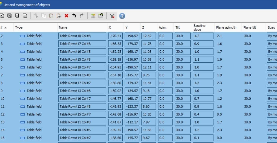
Thank you for the help. I have one more question. Is it possible to change "Plane Azimuth" and "Plane tilt" by editing ? Please see the attached screen where this data are not editable.
-
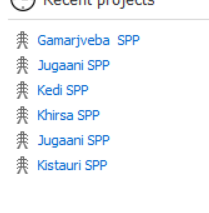
Hello, Projects with the same name and data appears in the soft. I tried to delete one of them but this causes emptying data from the second project. This happened 2 times in one day. Bellow screen shows 2 project with the same name "Jugaani SPP"
-
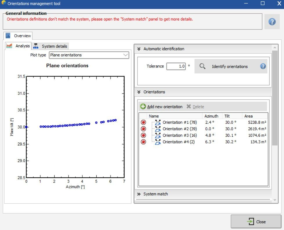
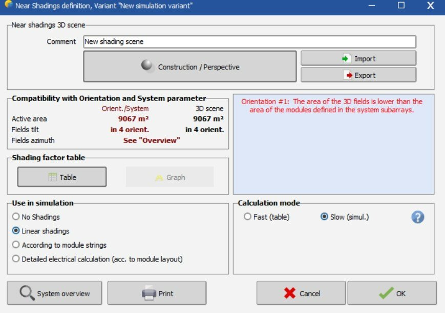
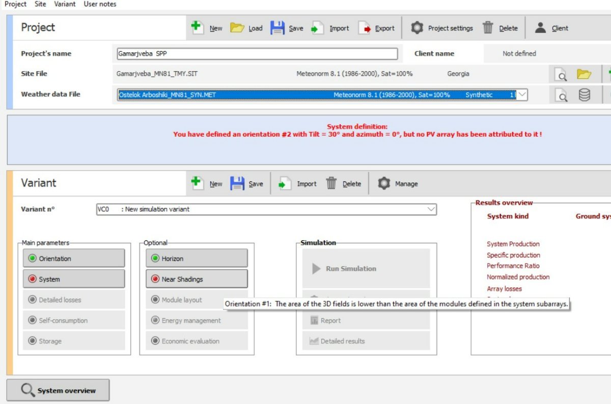
Hello, I imported PVC file from PVdesign successfully. In the "Near shading 3D scene" followed the following fields: "Shading field construction"-"Tools"-"Orientations Management", identified orientations (Result is attached, see file "Screenshot 1") and I received 4 different orientations. "Near shading 3D scene" page shows the following notification - "Orientation #1:"The area of the 3D field is lower than ......" (screen in attached, see file "Screenshot 2). Project first page screen is attached which shows mismatch between "System " and "Near Shading" (See attached file "Screenshot 3"). Can you please tell how to proceed? In forum page is written "After creating the orientations in the 3D scene (8 at most), you will have to harmonize them with those defined in the system and assign the subfields to these orientations", this may be the way but I can not find out how the subfields should be assigned to these orientation?
-
Hello, how should be subfields assigned to these orientation?
-
Hello, projects created in PVsyst demo version can be usable after purchasing license?
-
Does PVsyst have a function to display front-face and back-face energy yield and losses separately?
-
I downloaded PVsys demo version for study the system and testing. I created new project for which I have design prepared in other software (for comparision). In the PVsys "System production" is 1575 MWh/yr while the design shows 3270 MWh/yr. Input data are almost identical, indicated on fields "Orientation", "System", "Horizon" and partialy on "Detailed losses". Can you please check our project file, if I send it to you?