Loïs Masson
Members-
Posts
10 -
Joined
-
Last visited
Recent Profile Visitors
The recent visitors block is disabled and is not being shown to other users.
-
Hello, Does anyone know whether Meteonorm or SARAH3 is the most accurate database for France? Do you know of any scientific papers on this topic? Thank you in advance.
-
Hello, I would like to know if the following curve is taken into account during the simulation. Indeed, we can see that for this inverter, if the MPP imput Voltage is higher than 800V, the efficiency of the inverter is greatly reduced. I didn't find this curve into the .ond files. Should we put 800V instead of 1000V for the maximum MPP Voltage like in the picture below ? If we change that, I'm afraid that the inverter cannot produce any energy with an higher voltage. Thank you for your answer SUN2000-115KTL-M2 Output Characteristics Curve (400 480Vac).pdf
-
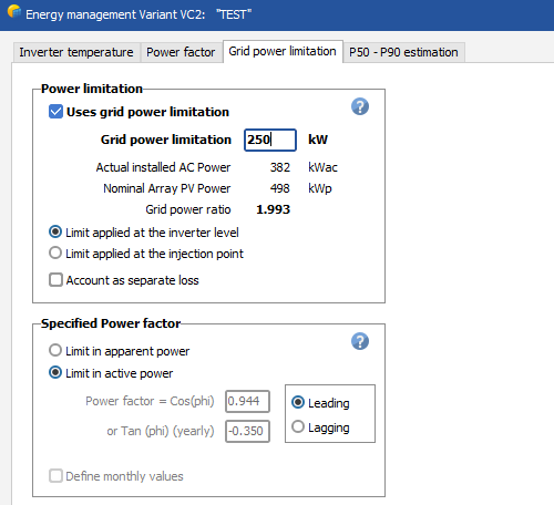
Hello, In France, low-voltage grid connections are only available for photovoltaic plants with an apparent power of up to 250 kVA. However, in some cases, we need to to use several inverters, resulting in a total installed power higher than 250kVA. In this situation, inverters are subject to a static power limitation of 250 kVA to comply with low-voltage grid connection constraints. What's the best way to simulate this limitation in PVSYST ? Should I simply define a grid power limitation ? or should I change the maximum power output of my inverters in the .ond files ? I have tested both approaches but the results are not the same I would appreciate your insights on the most accurate way to model this scenario. Best regards
-
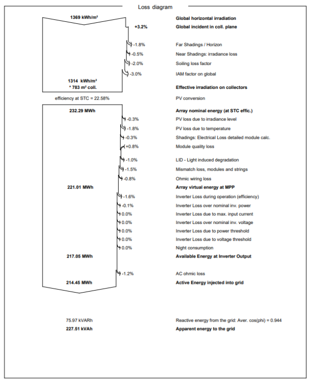
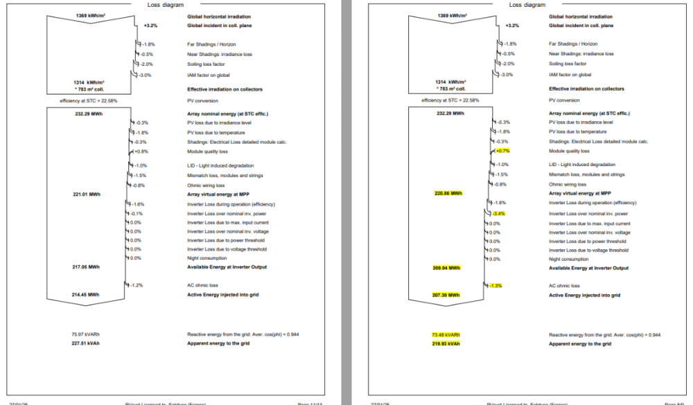
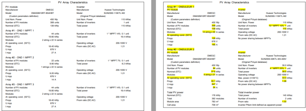
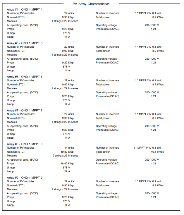
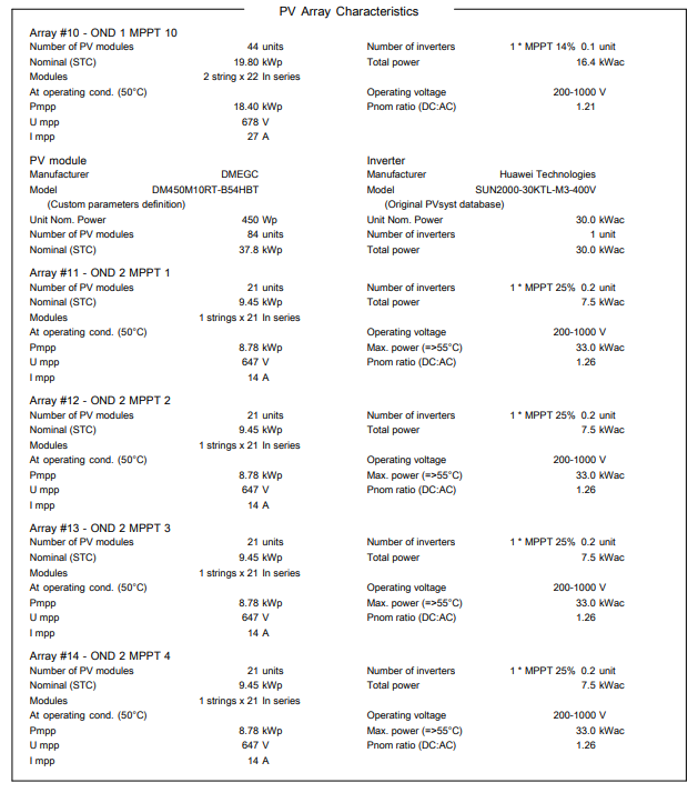
Hello, I noticed something in the software regarding inverter loss over nominal inv. power : The creation of a subfield for each MPPT in the system or t he grouping of multiple MPPTs into the same subfield leads to significant simulation differences (see the example below with an additional 3% in losses). How PVSYST manages the repartition of strings when we don't create a subfield for each MPPT ? Is there a trick to avoid creating a subfield for each MPPT (to save time) without generating these losses?
-
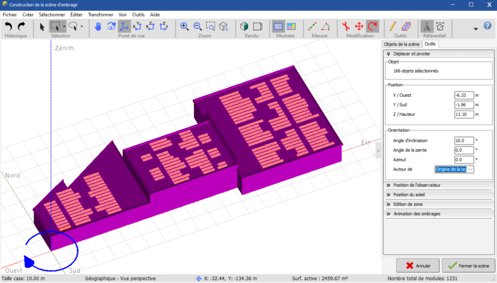
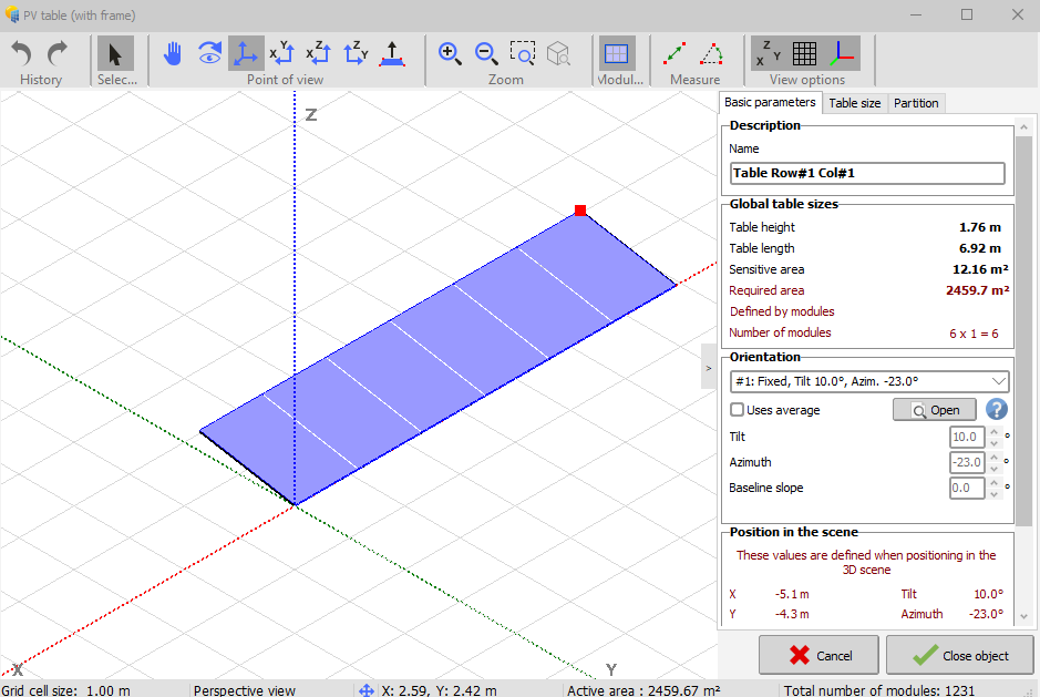
Hello, Before PVSYST 8.0, I used to create all my near shading scenes in the coordinate system X-Y, before rotating them around the scene origin, to get the real azimut of my project. In my opinion, it was easier to move all the componants just with their X and Y positions. But now, PV tables are already oriented according to their azimut and it's now longer and less precise to create near shadings scene. Have you a tips to solve this problem ? thanks
-
Hello, I work for a photovoltaic company, and sometimes we have to use .pan files provided by manufacturers (Jinko for example). But we always observe big differences between these files and those of the PVSYST database (especially for IAM loss). Even if these files are certified by SGS laboratory. So, I would like to understand what process is used by PVSYST to certify the conformity of .pan files integrated into the database. Do have you one or more laboratories that you work with, and that we can trust ? Thank you for your response !
-
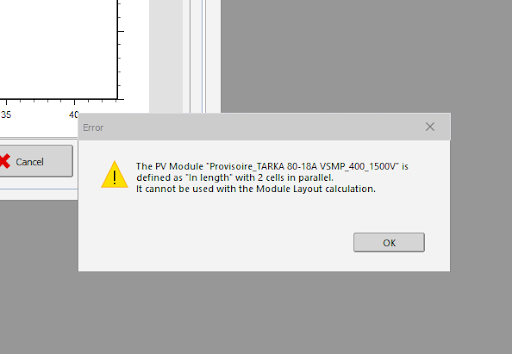
Hello, I can't do my module layout with the selected PV module, having this error (image1) "The PV module 'name' is defined as "in length" with 2 cells in parallel. It cannot be used with the Module Layout calculation." In the module settings, it is defined as "in width" and not in length. Here are the informations about the module (image2) Any solution ? Thanks
-
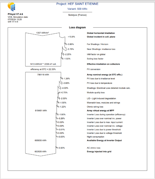
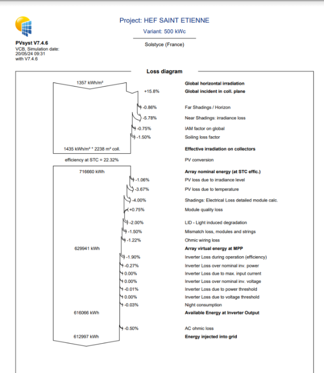
Hello, I would like to know if the solar panel are tested before being integrated into the database ? For the same project, I created 2 variants, one with the .pan file of the JINKO JKM445-54HL4R-V included in your databased, and another one with a .pan file of the same panel but sent by JINKO. As you can see in the 2 graphs below, there is a huge difference between the 2 losses due to the IAM factor. I imagine that .pan files included in the database are more precise, but does it mean that we cannot trust manufacturers when they send us .pan file ? Thank you in advance for your answer !



.png.a8a4902dbd67e58f6ff6087567979232.png)
