AmsteinWalthert
-
Posts
4 -
Joined
-
Last visited
-
Thank you for the explanation and answer. I suggest, the described interpolation effect shows only in the graph and not in the calculation itself? I suggest there the 3D Scene is used as basis? One more detailed question: is the shown Albedo value in the iso-shading diagram the yearly average weighted by energy? Or how can it be interpreted?
-
Thank you for the explanation and answer. One more detailed question: is the shown Albedo value in the iso-shading diagram the yearly average weighted by energy? Or how can it be interpreted?
-
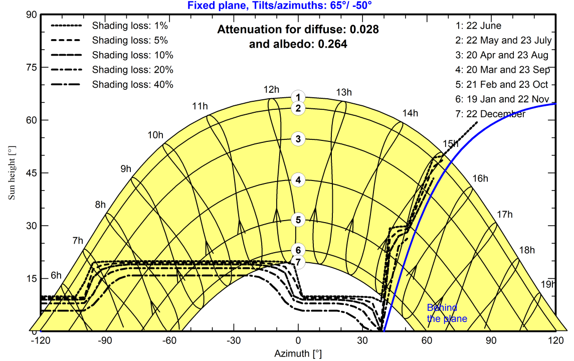
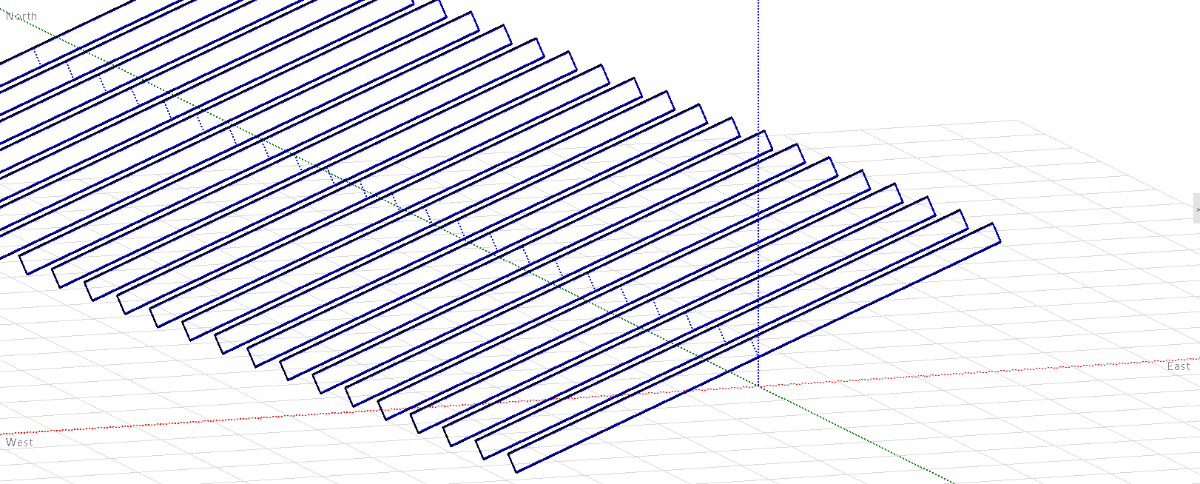
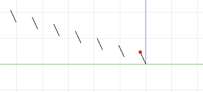
Another question regarding the iso shading diagram and its interpretation. We simulated a bifacial system 65° tilted and -50° east oriented on a sloped hill with 17.9° according to the images below. Questions for the iso shading diagramm: Why is there still partial shading at sun heigths > 15° even though the limit angle is set to 15° in the 3D-scene? How can the plateau from azimuth angles -100 to 0 be explained? Why is it flat and not more round? Why does it go all the way till 0° azimuth and drops not already at -50°? Is the answer somehow related to this second post here? Thank you very much Best S

-
Hi. I defined a bifacial system (2D-model unlimited sheds) and a 3D construction in the near shading. The shed to shed slope in the 3D construction is >0° and hence the limit profile angle different as in the bifacial system with a slope of 0°. For the shading losses the slope of the 3D construction is used in the calculations. But for the bifacial gain it, seems a slope of 0° ist used. How to solve this problem? And: in the result report the limit profile angle of the bifacial system definietion in used and not the one from the 3D construction. How to solve this bug? Thank you very much! Best M