


Katinka89
-
Posts
9 -
Joined
-
Last visited
Posts posted by Katinka89
-
-
Hello,
Thank you very much for your quick reply!
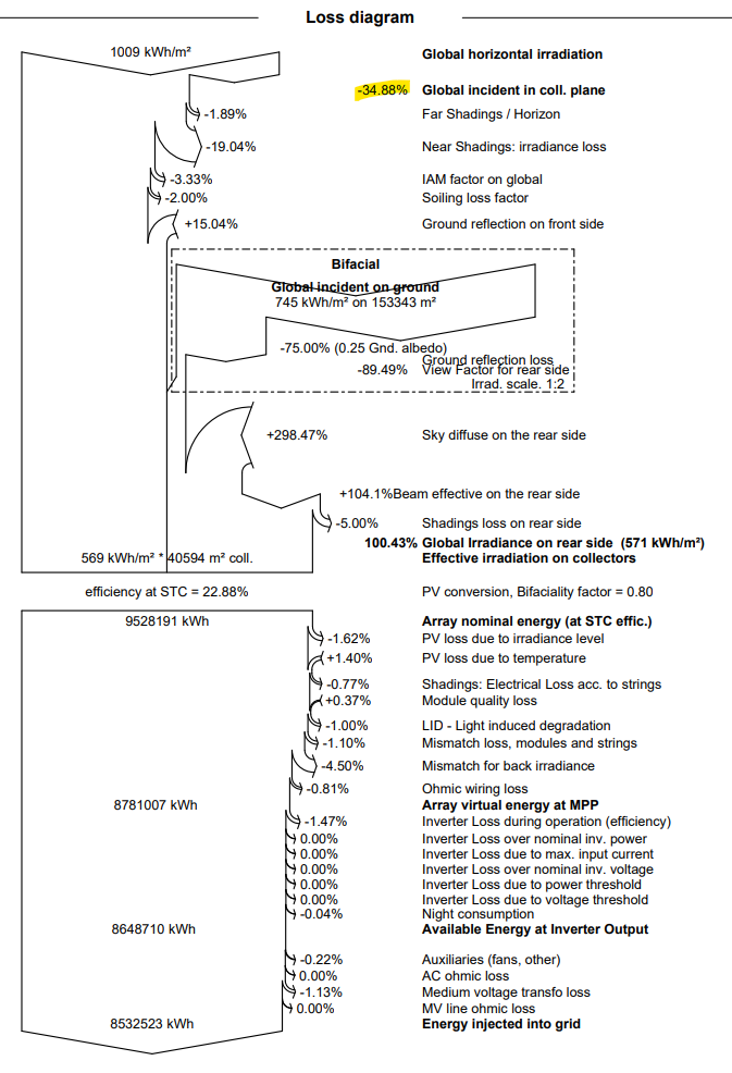
I have another question regarding the simulation of a vertical east-west system with bifacial modules:
As can be seen in the loss diagram above, it results in very high values for sky diffuse and beam effective on the rear side.
I suspect that this is due to the vertical system. Is the result of the energy output nevertheless correct?
Thank you very much!
-
Hello,
we would like to simulate a plant as a vertical system with bifacial panels.
Our loss diagram looks like this:

We are wondering why we have a negative value for the global incidence in collector plane. Is it because we have a tilt of 90 degrees?
We would appreciate a brief explanation.
Thank you very much!
Janne
-
Hello,
We have the same problem:
a vertical system with a pitch of 10m leads to near-shadings of -19% (that seems quite high to us).Does anyone have any idea what this could be due to?
Thank you very much!
Janne
-
Hello again,
thank you very much for your answers!
I have now done the following:
For each cable segment I calculated the loss fraction:
MVPS1-MVPS2: 0.07%.
MVPS2-MVPS3: 0.06%.
MVPS3-MVPS4: 0,09%.
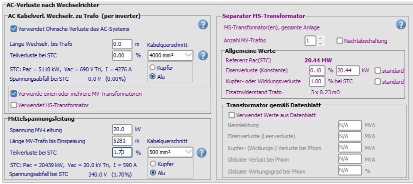
MVPS4 - feeding point: 1,48%.
So the total loss fraction is 1.7%.
I add this value to the detailed losses and assume that I have a transformer with a percentage value for the iron loss: 0.1% and for the
copper losses: 1.0%.Is this correct?
Thanks you

-
Dear dtarin,
thank you very much for your quick reply.
I already know this procedure. I then enter the weighted average of the losses and only one transformer and add all the no-load and full-load losses of the transformers. Is this correct?
I just wonder if it is also possible to calculate the weighted average of the lengths to run the simulation?
Because in PVSyst, under detailed losses, you have the option to enter either the length of the wire or the loss fraction.
-
Dear Muhammed,
sorry, that was confusing. I didn't mean series connection in the electrical sense. But the four MVPS are connected in such a way that the segments between them carry different power. The first carries 1/4 of the total power, the second half, the third 3/4, and the last the total power.
We want to calculate the total losses of the mv line, both for the mv lines between the transformers and for the mv line between the last MVPS and the feed point.
Here are the lengths:
MVPS1-MVPS2: 0.431 km
MVPS2-MVPS3: 0.192 km
MVPS3-MVPS4: 0.369 km
MVPS4 - injection point: 7.84 km
Best regards -
Hello,
we are planning some MW plants with central inverters, more precisely medium voltage power stations combining inverter and medium voltage transformer.
Now we want to calculate the MV line losses and we are not sure how to specify.
In one project, we have four MVPS connected in series and then connected to the feeding point. We know the distances between the MVPSs and the distance to the feed point.
How can we calculate the loss correctly? Should we use four transformers and the average length to the feed point?
Or one transformer? Then what length do we need to insert?
I hope that the question is understandable ...
Thank you!
-
Hello!
I hope someone can help me with this issue:
I have a multi MPPT inverter with 12 MPPT, each tracker has two inputs.
How can I assign certain strings (same shading situation) to a tracker?
I know that I can assign modules to strings in the module layout, but how can I assign these strings to an input of the inverter?
Thanks a lot in advance!
Janne
Vertical system with bifacial panels > negative Global incident in collector plane
in Simulations
Posted
Hello Linda,
thank you for your quick reply and the link to your tutorial, which is also very helpful.
Nevertheless, I wonder if our results could be correct.
We are planning a system with these parameters:
- vertical bifacial
- East West orientation
- height above ground: 0.8 m
- pitch: 10 m
and would like to compare the results with a standard south-facing system.
Thank you very much!
Janne